
The basis of a simple anemometer is a processor fan that worked from a voltage of 5V. The impeller is cut from an old compact disc.
The tachometric sensor outputs 4 pulses. Per revolution. If everything is put together, then the anemometer head makes 2.5 pulses per meter of passing air.
It remains to determine how many pulses came in 1 second, divide by 2.5 and get the wind speed in meters per second.
The question of electronics can be solved with a puzzle, but on the microcontroller this is done very simply. The diagram below.
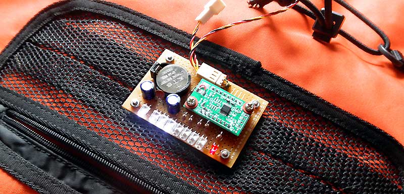
All that is to the left of the CN1 connector is in the sensor. The capacitor C2 cuts the interference that can occur in the wires. R3, C3 reset circuit. R4-R8 limit the current through the LEDs. The circuit is powered by a lithium battery CR2032 (220mA / h) and consumes from 1.5mA to 7mA.
The microcontroller operates in the frequency meter mode. Every second he updates the data on the screen of 8 LEDs. If there are less than 3 pulses, the screen is turned off. If 3, then the first LED (1m / s) is lit, if 5, then the first and second (2m / s), and so to 8. If the speed is more than 8m / s, the ruler of the burning LEDs will mix to the right. The red LED ("Monitor") lights up twice per turn of the impeller.
In the circuit will work with any microcontroller from the MSP430 series, with a P1.x port of 8 bits. MSP430F2011 - just because I have it.
For programming, MSP430 Launchpad is required, to which the controller is connected ( four wires ) through the CN2 connector, and the CCS program of any version (free of charge from TI). We copy the contents of the text file Anemometer_MSP430any_for_sensor_2_5_turns_per_meter_C_file.txt in Code Composer Studio, click the icon with the image of the beetle and the program merges into the microcontroller. We disable Launchpad, connect the anemometer sensor, install the battery and the scheme "ready for battle".
From now on, you have in your hands a ready anemometer that shows the wind speed from 1 to 16 m / s.
End of story :)
9. Then you can not read.
I do not answer e-mail, there is no time. Therefore, the answers to the questions that you may be interested in are below.
9.1 Sensor.
The speed of rotation of the anemometer blades directly depends on its geometry. If you made an impeller from a compact disc, then the distance between the axis of rotation and the center of the blade will be 45-50mm. At the same time, no matter how crooked you all have done, the rotor will make a full revolution for 1.6m of past air.
The speed of stitching depends on the quality of the bearings and the area / geometry of the blades.
9.2 About the program.
The program works as follows. The microcontroller is configured, WDT interrupts are enabled by changing the voltage at input P1.7, and goes to "sleep". For WDT it remains to operate an internal oscillator of 12 kHz. // WDT ( W atch D og T imer) works like a normal timer.
If the voltage changes at the input P1.7 (Hi / Low), the microcontroller wakes up, adds 1 to the pulse counter from the sensor, switches the red LED (D1) and goes to sleep again.
The interruption from the WDT wakes the microcontroller 164 times per second. Each even-numbered time data is output to the LEDs D2-D5, odd-D6-D9. In addition, for each 164th interrupt (1 second passed), the microcontroller recalculates the data that is output to the LEDs and zeroes the pulse counter from the sensor. And falls asleep.
In order not to work with fractional numbers, the conversion factor of the pulses into meters of the past air is multiplied by 2. Also, by 2, the number of pulses arriving from the sensor is multiplied.
To recalculate the wind speed into the number of burning LEDs, the following is done. In the 16-bit variable, 8 units are put in the lower order (0b0000000011111111) and shifted to the left by the wind speed value. For 5 m / s the result is 0b0001111111100000. After that, no matter what, the result is shifted to the right, 8 times. We get five units in the lower order or 0b0000000000011111. The result, 0b00011111, is sent to the indicator.
Since a cyclic shift is used, after 8 m / s the result will be shown by the LEDs turned off.
9.3 Consumption current.
From the CR2032 (3V) lithium battery, the microcontroller consumes <0.2mA, the sensor is -1.5mA, all the LEDs are up to 5mA. In total about 7mA (max).
9.4 To feed from what and how.
Estimated power supply for MSP430, by it self, from 1.8V to 3.6V. Green and red LEDs require 1.6V, white - 2.6V.
9.5 Up to what frequency from the sensor the circuit continues to work without failures.
Theoretically, the maximum frequency is about 2 kHz (not more than 10 kHz, that's for sure). This is due to the fact that every time the microcontroller goes out of sleep mode, it should start the internal oscillator ~ 1 MHz, and this takes a time.
9.6 Do the same, but on Arduino.
It is possible, but Arduino is not "imprisoned" for low power consumption.
9.7 Accuracy.
Indeed, if you repeated everything one-on-one, then the accuracy will be plus or minus 20%. But for a kayak, this mistake does not make any difference.