Replacing the shutter curtains in the camera Canon XSi.
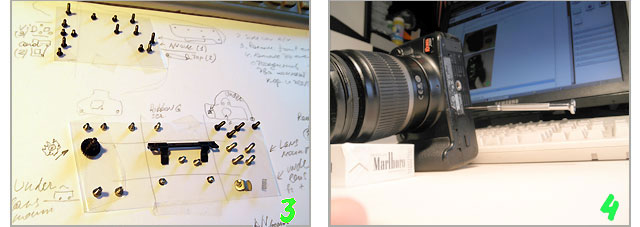
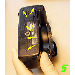
To change the shutter curtain in the camera Canon XSi (450D), on their own, you will need a good screwdriver that exactly matches the slot screws (all screws have the same head). If, the screwdriver, does not fall out of the screw, as shown in picture 4, it is exactly what we need. Plus, ALL screws and small parts that are removed from the camera should be stacked on pieces of transparent adhesive tape and signed, as shown in picture 3. This slows down the disassemble, but accelerates the assembly of camera. And the "extra parts" does not remain. Thin rubber gloves - is desirable. They protect your camera from your fingerprints and you, from a high voltage, which can be present in some places of the camera.
Photos below show how I did. This is not the shortest way, but the curtains are replaced and the camera works well. In general, the sequence should be like that.
1. Remove the back cover and disconnect all the available connectors.
2. Remove the front cover, disconnect another 4 connectors.
3. Remove the top cover.
4. Remove USB bracket and two rear circuit boards.
5. Disconnect one connector, remove image sensor and adjusting pads.
6. Remove the aluminum frame (get access to the mechanism of camera shutter).
7. Unscrew two screws, and change the shutter curtain.
Adjustment items - three different sets of shims, under the image sensor. They need to be removed and put exactly in each place.
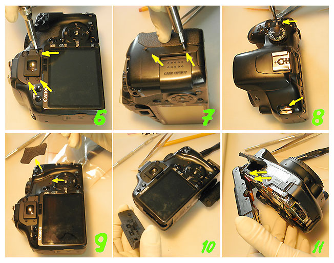
 In the beginning, after removing the battery and SD card, start to gently unscrew all the screws, as shown by arrows in the photographs.
If you find any more black screws, then unscrew them the same.
Carefully put all the pieces in a clear "tape" and sign. It should look like in the upper left corner of the picture (3).
Decorative plastic plate (9), the same shoot, picked up at one end with forceps. Under it there are no screws, but it connects the two plastic parts of the camera body.
After that, slowly separate the back cover of the screen, gently rocking from side to side (11). Under it no secret latches and extra screws, but there is a flat cable, which should be not damaged.
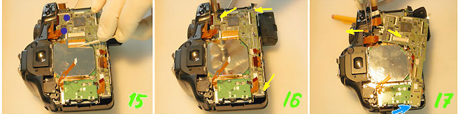
When the electronics board is removed (18), it's time to remove the front cover of the camera. It is attached to the four screws (19). Last one is hidden under the rubber grip (20). Actually, the front cover had to be removed immediately after the rear cover. Then there is access to the screw marked on photos (17), a blue arrow. If you unscrew the screw and remove USB bracket, the electronics board is much easier to remove.
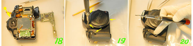
Remove the four screws (19), the latter of which is hidden under the rubber grip (20), can remove the front cover. Screw optical corrector (18), the last thing that keeps the top cover (have to disconnect a few connectors, see photo 30).
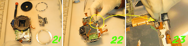
Then, as shown in photo 21 - was taken out by mistake. 22 and 23 - the last connector, which must be disconnected before removing the photo sensor.
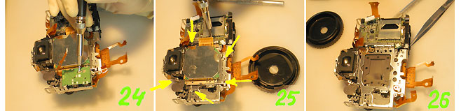
After removing a small board (24), we get access to the last sensor mount screw. Unscrew five screws and carefully lift the sensor. Under the three long screws are adjusting shims, which is exposed position sensor.
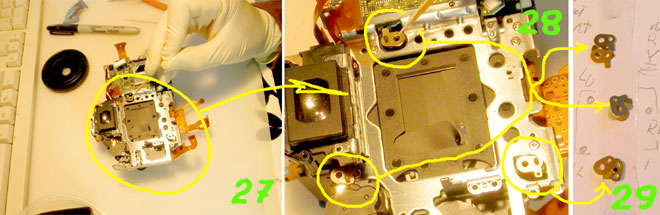
Lack of or the right combination of these shims affects the adjustment definition images. So, take out all shims (27, the same increased only 28) and add on a piece of transparent tape "(29). Next, immediately sign all shims and theirs position to the sequence, as where they lay.
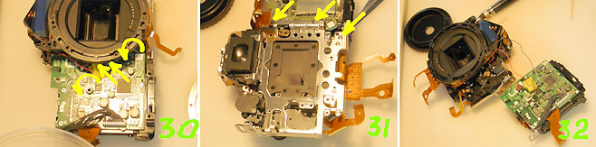
Two connectors, which are shown by straight arrows in photo 30, has been disconnected when we remove the top cover with the flash. The remaining two connectors - turn arrow and detach from the board. It remains, to unscrew the screw three (31) and disconnect the battery unit (32).
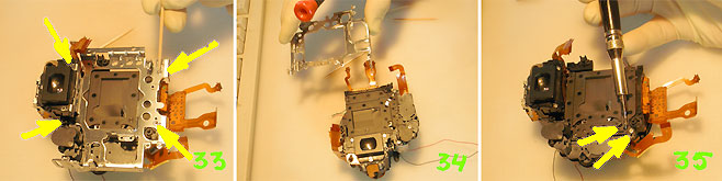
The frame is mounted on the four screws (33). Some problems with the screw, which is located on the left of the viewfinder (33 - left, bottom). Screwdriver, into it, comes at a slight angle (prevents the viewfinder). However, you unscrew it with no problems. Remove the frame and unscrew two screws (35).
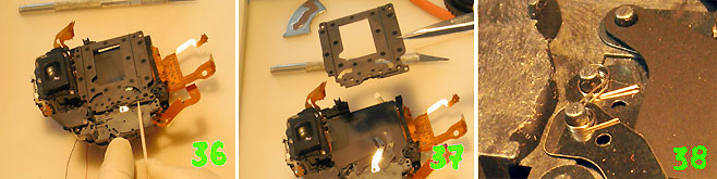
The black frame is shifted in the direction of a toothpick (36) and very carefully removed (37). Why CAREFULLY? Underneath are two steel springs, and very, very small. They keep the curtains. Without them, the shutter will not work. When I examined the camera, one of the springs come off, fly away and then disappeared. I have it, of course found, but an hour later, on the floor and three meters away from the table. I was lucky that the floor had light color. Photo 38 will help you when you install the springs in place.
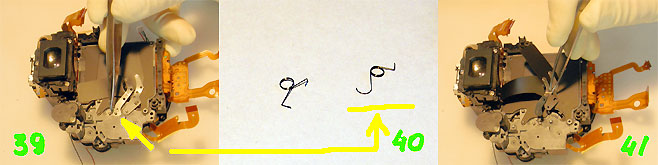
39 - Carefully remove those springs. First removed the rear curtain spring. This spring is highlighted in the photo 40. Then, carefully remove the rear curtain and front curtain spring. It is better to keep a strong magnet nearby, just in case.
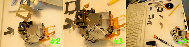
The dividing plate (42), the front curtain (43) and the dismantling of the camera is over. Congratulations.

45 - Springs will be installed in such a position. 46 - Set the shutter and the front spring. 47 - Set up intermediate plate.
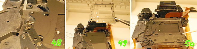
48 - Rear curtain with a spring. After installing the springs - do not pull or push, and do not move shutter or curtains. Immediately cover with a curtain exterior plate (49), which presses down and moves a side with a toothpick (50).
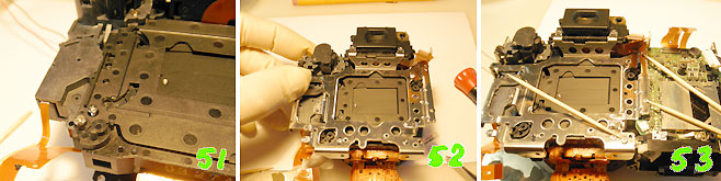
Tighten the two screws (51). At the same time, resuscitation shutter is finished!
Next, install aluminum frame (52), and battery unit (53).
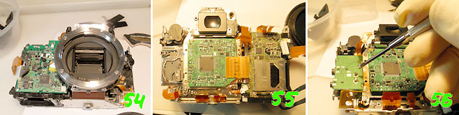
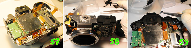
Photos 54 - 59 ... Assembling the camera, starting with Photo 31, only in reverse.
In conclusion.
In my case, the camera will start to work immediately after installation of the lens, battery and SD-card. Once on, she snapped (apparently set the shutter and mirror hung) and asked to set the time. Photo (leaf in the box) showed excellent sharpness across the frame. And the "Error 99" - the camera is no longer recalls.
Of course, to repair the camera yourself - risky. But in the case of the old camera, when repair shop asking for an inordinate amount of money, it makes sense. Win more than we lose. In the worst case, you can sell yours camera body, to repair shop, for $ 50.
Let's see what bad can happen with self-repair.
1. With a bad screwdriver, you can cut the heads of screws and camera lose a good appearance. Treated the presence of a good screwdriver.
2. You can leave dirt on the sensors, mirrors and so on. If you work in the fresh rubber gloves, then from this problem you will be protected. And the dust - the camera will take care of it, yourself.
3. You can break connectors latches. You can. But to do so much hard work. Even in this case, the connectors can be restored.
4. Break the ribbon cable. A cable break - not simple. You can cut it on the sharp edge of the plastic or metal parts - very easy. Simply, this should not be tolerated.
5. Wrong plug connectors. It is not possible, all the connectors are different. Another thing - do not fully insert the cable into the connector. This is very possible. Therefore, all connections must be double checked.
6. You can knock down the factory settings. Of all the settings that you can break, only the position of the senor, which is exposed at the factory with a set of shims. These shims must be removed and put each in its place during assembly. The factory settings are, thus, remain.
7. When replacing the need to completely reprogram the camera. When replacing the shutter complete - perhaps, but in case of replacement shutter curtains - no need to do it.
Materials that have helped me and will help you.
Canon Service Manual for similar cameras was found on the Travis' Blog, page (free). Copy, just in case: 7Z01, +7Z02, +7Z03 .
To change the shutter curtain in the camera Canon XSi (450D), on their own, you will need a good screwdriver that exactly matches the slot screws (all screws have the same head). If, the screwdriver, does not fall out of the screw, as shown in picture 4, it is exactly what we need. Plus, ALL screws and small parts that are removed from the camera should be stacked on pieces of transparent adhesive tape and signed, as shown in picture 3. This slows down the disassemble, but accelerates the assembly of camera. And the "extra parts" does not remain. Thin rubber gloves - is desirable. They protect your camera from your fingerprints and you, from a high voltage, which can be present in some places of the camera.
Photos below show how I did. This is not the shortest way, but the curtains are replaced and the camera works well. In general, the sequence should be like that.
1. Remove the back cover and disconnect all the available connectors.
2. Remove the front cover, disconnect another 4 connectors.
3. Remove the top cover.
4. Remove USB bracket and two rear circuit boards.
5. Disconnect one connector, remove image sensor and adjusting pads.
6. Remove the aluminum frame (get access to the mechanism of camera shutter).
7. Unscrew two screws, and change the shutter curtain.
Adjustment items - three different sets of shims, under the image sensor. They need to be removed and put exactly in each place.
Digital camera Canon XSi. Disassemble.
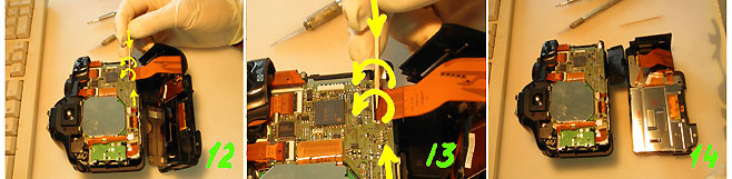
In the beginning, after removing the battery and SD card, start to gently unscrew all the screws, as shown by arrows in the photographs. If you find any more black screws, then unscrew them the same.
Carefully put all the pieces in a clear "tape" and sign. It should look like in the upper left corner of the picture (3).
Decorative plastic plate (9), the same shoot, picked up at one end with forceps. Under it there are no screws, but it connects the two plastic parts of the camera body.
After that, slowly separate the back cover of the screen, gently rocking from side to side (11). Under it no secret latches and extra screws, but there is a flat cable, which should be not damaged.
To detach the flat cable from the camera board, you must use two toothpicks. Pry brown latch and turn it in the direction of the arrows show (13).
When the electronics board is removed (18), it's time to remove the front cover of the camera. It is attached to the four screws (19). Last one is hidden under the rubber grip (20). Actually, the front cover had to be removed immediately after the rear cover. Then there is access to the screw marked on photos (17), a blue arrow. If you unscrew the screw and remove USB bracket, the electronics board is much easier to remove.
Remove the four screws (19), the latter of which is hidden under the rubber grip (20), can remove the front cover. Screw optical corrector (18), the last thing that keeps the top cover (have to disconnect a few connectors, see photo 30).
Then, as shown in photo 21 - was taken out by mistake. 22 and 23 - the last connector, which must be disconnected before removing the photo sensor.
After removing a small board (24), we get access to the last sensor mount screw. Unscrew five screws and carefully lift the sensor. Under the three long screws are adjusting shims, which is exposed position sensor.
Lack of or the right combination of these shims affects the adjustment definition images. So, take out all shims (27, the same increased only 28) and add on a piece of transparent tape "(29). Next, immediately sign all shims and theirs position to the sequence, as where they lay.
Two connectors, which are shown by straight arrows in photo 30, has been disconnected when we remove the top cover with the flash. The remaining two connectors - turn arrow and detach from the board. It remains, to unscrew the screw three (31) and disconnect the battery unit (32).
The frame is mounted on the four screws (33). Some problems with the screw, which is located on the left of the viewfinder (33 - left, bottom). Screwdriver, into it, comes at a slight angle (prevents the viewfinder). However, you unscrew it with no problems. Remove the frame and unscrew two screws (35).
The black frame is shifted in the direction of a toothpick (36) and very carefully removed (37). Why CAREFULLY? Underneath are two steel springs, and very, very small. They keep the curtains. Without them, the shutter will not work. When I examined the camera, one of the springs come off, fly away and then disappeared. I have it, of course found, but an hour later, on the floor and three meters away from the table. I was lucky that the floor had light color. Photo 38 will help you when you install the springs in place.
39 - Carefully remove those springs. First removed the rear curtain spring. This spring is highlighted in the photo 40. Then, carefully remove the rear curtain and front curtain spring. It is better to keep a strong magnet nearby, just in case.
The dividing plate (42), the front curtain (43) and the dismantling of the camera is over. Congratulations.
45 - Springs will be installed in such a position. 46 - Set the shutter and the front spring. 47 - Set up intermediate plate.
48 - Rear curtain with a spring. After installing the springs - do not pull or push, and do not move shutter or curtains. Immediately cover with a curtain exterior plate (49), which presses down and moves a side with a toothpick (50).
Tighten the two screws (51). At the same time, resuscitation shutter is finished!
Next, install aluminum frame (52), and battery unit (53).
Photos 54 - 59 ... Assembling the camera, starting with Photo 31, only in reverse.
In conclusion.
In my case, the camera will start to work immediately after installation of the lens, battery and SD-card. Once on, she snapped (apparently set the shutter and mirror hung) and asked to set the time. Photo (leaf in the box) showed excellent sharpness across the frame. And the "Error 99" - the camera is no longer recalls.
Of course, to repair the camera yourself - risky. But in the case of the old camera, when repair shop asking for an inordinate amount of money, it makes sense. Win more than we lose. In the worst case, you can sell yours camera body, to repair shop, for $ 50.
Let's see what bad can happen with self-repair.
1. With a bad screwdriver, you can cut the heads of screws and camera lose a good appearance. Treated the presence of a good screwdriver.
2. You can leave dirt on the sensors, mirrors and so on. If you work in the fresh rubber gloves, then from this problem you will be protected. And the dust - the camera will take care of it, yourself.
3. You can break connectors latches. You can. But to do so much hard work. Even in this case, the connectors can be restored.
4. Break the ribbon cable. A cable break - not simple. You can cut it on the sharp edge of the plastic or metal parts - very easy. Simply, this should not be tolerated.
5. Wrong plug connectors. It is not possible, all the connectors are different. Another thing - do not fully insert the cable into the connector. This is very possible. Therefore, all connections must be double checked.
6. You can knock down the factory settings. Of all the settings that you can break, only the position of the senor, which is exposed at the factory with a set of shims. These shims must be removed and put each in its place during assembly. The factory settings are, thus, remain.
7. When replacing the need to completely reprogram the camera. When replacing the shutter complete - perhaps, but in case of replacement shutter curtains - no need to do it.
Materials that have helped me and will help you.
Canon Service Manual for similar cameras was found on the Travis' Blog, page (free). Copy, just in case: 7Z01, +7Z02, +7Z03 .