
17. Simple electronic devices.
17.18 Universal (120VAC/12-24VDC) Li-Ion Battery Charger.
In accordance with the technical data on back side of this charger, we can use a 12V solar panel to charge Li-Ion battery, but it will be known after we get the circuit diagram.
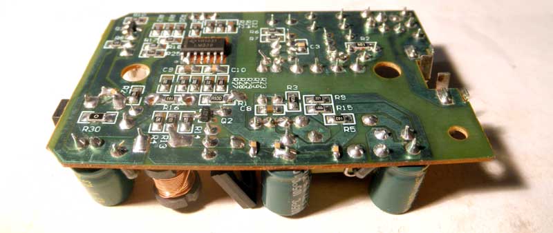
And the bottom side.
Actually, all chargers for lithium batteries work the same way. They limit charging current, and do not allow to charge Li-Ion battery to more than 4.2 Volts. The battery is considered fully charged if the charging current is reduced by 10 times or so. This is simple and good explained in the Application Report SLAA287 “Li-Ion Battery Charger solution using the MSP430”, from Texas Instruments (slaa287.pdf).
The following schematic diagram shows how this charger works. From left to right, four independent circuits: AC-DC converter, +2.5V source, PWM charging circuit and charging indicator with 2 LEDs.
The AC-DC converter works as described in the datasheet for AP8012. The divider R15,R5 determine output voltage level (about 13V on C6). Power (12V or so) can be delivered from the outside, through the CN2.
IC5 (TL431) – source of stable +2.5V for measuring circuit on IC4 (LM339 – 4 comparators with 'open collector' outputs).
Q1,Q2, IC4.2, IC4.1 – PWM charging circuit. It operates as follows. When power is supplied, both transistors are opened and the current flowing through the inductor L2 and D10 to the load. Two events can stop it: the voltage on divider R27, R28||R29 exceeds 4.24Volts (by IC4.2) or current through the resistor R1 exceeds 0.45Amps (by IC4.1). The low level on outputs of IC4.1/4.2 turns transistor off and power collected in core of L2 flows to the load (for short tine). After L2 discharged, voltage / current drops and the cycle is repeated.
Charging indicator works much easier. It is a comparator (IC4.3) with hysteresis (by add R21). When power ON and no battery, voltage on inverting input (-) is close to 0V, on non-inverting input (+) close to 13mV (because of divider R21||R22&R24). Output is Hi, Q3 and green LED is ON.
Charging the battery with current more than 0,13A (>13mV on pin 10, IC4.3) switches comparator output to Low, RED LED is ON, GREEN – OFF. Same moment, voltage on pin 11 drops to 7mV, and the charging indicator will changes its state when the charge current will drops to less then 0.07A. At this point, the battery is considered fully charged.
Waveform pulses at the collector of transistor Q1 shows how this circuit works. For the two load currents (0,2A & 0.01A) it's on photos below (zoom it if you want).
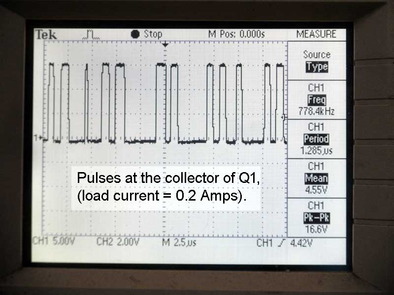
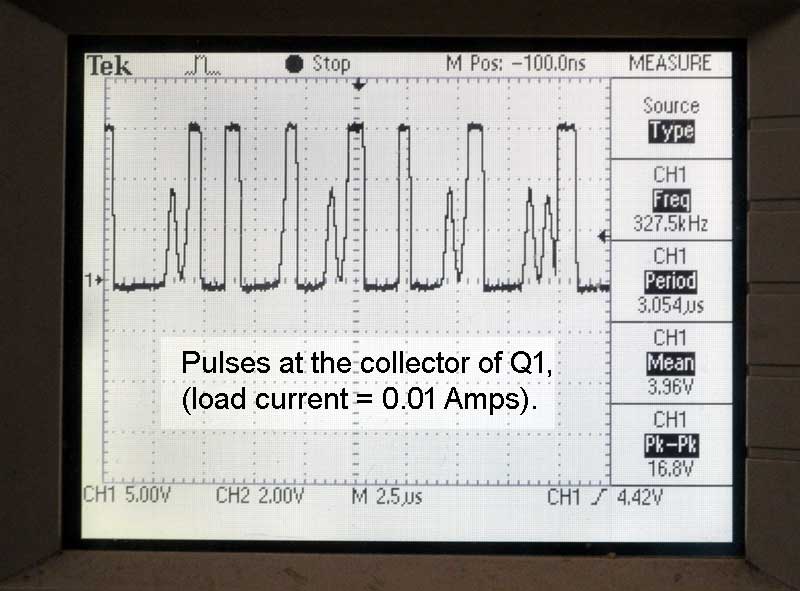
I do not like these pulses, but the system is running properly at 12.6VDC.
I'm going to feed the charger from 12V solar panel, and I'm interested in DC voltage limit for this device. And it looks like the circuit has two components that limit this:
- capacitor C6 has 16V limit,
- the current through the optocoupler's LED (IC4) exceed 50mA after 16V.
The problem is that the 12-volts solar panels never produce precisely 12 volts ...
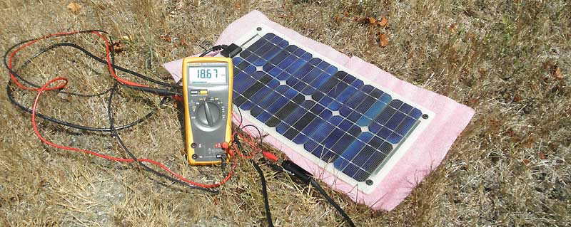
And, of course, my solar panel not an exception, and produce a little more voltage at idle.
Simple addition to the circuit solves 'Hi voltage' problem and allows to operate reliably. In addition, new circuit does not consume extra current through IC4 and IC2, when powered by an external DC.
D8 separates AC and DC circuits, C7 required for normal operation of buck converter on Q1, C13-C16 - just a good practice to reduce RF noise.
Together with adding missing elements (D8,C7), all low voltage electrolytic capacitors have been replaced too. Thank that this charger has a some extra space in the middle.
Finally, changes have been made and I can reliably use it with my solar panel.
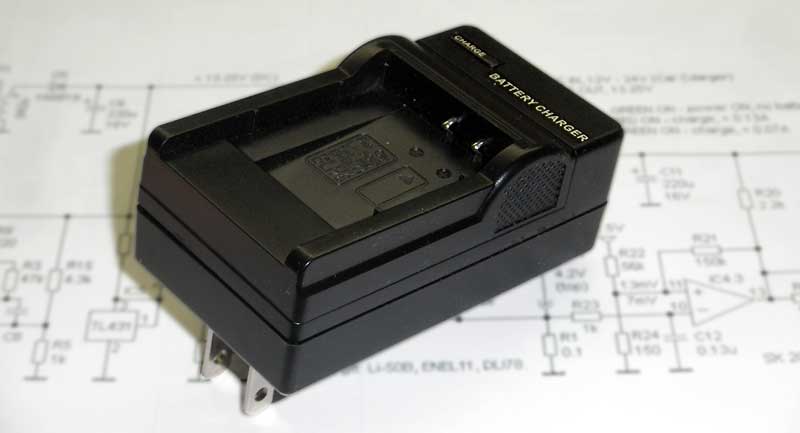
It is another LI-Ion battery charger, which a little bit does not work. In this case, I burn it by mistake. And, it is a good chance to see what inside.
It was designed to charge Li-Ion batteries for Olympus (LI-50B), Nikon (ENEL11) and Pentax (DLI78).
Working from 120VAC or 12VDC, does not care about battery temperature, and does not know anything about the battery, which recharges.
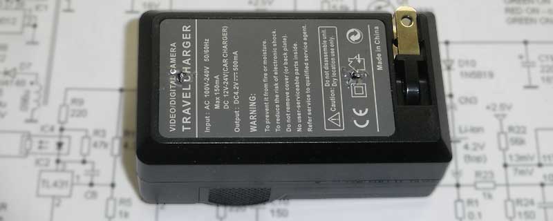
In accordance with the technical data on back side of this charger, we can use a 12V solar panel to charge Li-Ion battery, but it will be known after we get the circuit diagram.
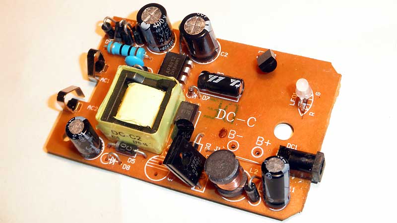
OK. It is a top view of internal board (D8,C7 - missing).
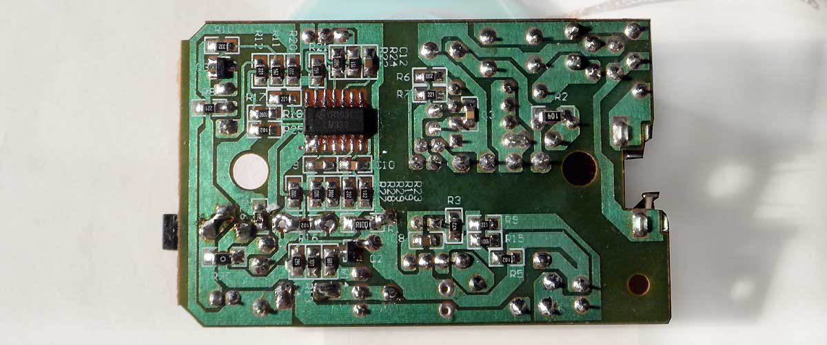
And the bottom side.
Actually, all chargers for lithium batteries work the same way. They limit charging current, and do not allow to charge Li-Ion battery to more than 4.2 Volts. The battery is considered fully charged if the charging current is reduced by 10 times or so. This is simple and good explained in the Application Report SLAA287 “Li-Ion Battery Charger solution using the MSP430”, from Texas Instruments (slaa287.pdf).
The following schematic diagram shows how this charger works. From left to right, four independent circuits: AC-DC converter, +2.5V source, PWM charging circuit and charging indicator with 2 LEDs.
IC5 (TL431) – source of stable +2.5V for measuring circuit on IC4 (LM339 – 4 comparators with 'open collector' outputs).
Q1,Q2, IC4.2, IC4.1 – PWM charging circuit. It operates as follows. When power is supplied, both transistors are opened and the current flowing through the inductor L2 and D10 to the load. Two events can stop it: the voltage on divider R27, R28||R29 exceeds 4.24Volts (by IC4.2) or current through the resistor R1 exceeds 0.45Amps (by IC4.1). The low level on outputs of IC4.1/4.2 turns transistor off and power collected in core of L2 flows to the load (for short tine). After L2 discharged, voltage / current drops and the cycle is repeated.
Charging indicator works much easier. It is a comparator (IC4.3) with hysteresis (by add R21). When power ON and no battery, voltage on inverting input (-) is close to 0V, on non-inverting input (+) close to 13mV (because of divider R21||R22&R24). Output is Hi, Q3 and green LED is ON.
Charging the battery with current more than 0,13A (>13mV on pin 10, IC4.3) switches comparator output to Low, RED LED is ON, GREEN – OFF. Same moment, voltage on pin 11 drops to 7mV, and the charging indicator will changes its state when the charge current will drops to less then 0.07A. At this point, the battery is considered fully charged.
Waveform pulses at the collector of transistor Q1 shows how this circuit works. For the two load currents (0,2A & 0.01A) it's on photos below (zoom it if you want).
I do not like these pulses, but the system is running properly at 12.6VDC.
I'm going to feed the charger from 12V solar panel, and I'm interested in DC voltage limit for this device. And it looks like the circuit has two components that limit this:
- capacitor C6 has 16V limit,
- the current through the optocoupler's LED (IC4) exceed 50mA after 16V.
The problem is that the 12-volts solar panels never produce precisely 12 volts ...
And, of course, my solar panel not an exception, and produce a little more voltage at idle.
Simple addition to the circuit solves 'Hi voltage' problem and allows to operate reliably. In addition, new circuit does not consume extra current through IC4 and IC2, when powered by an external DC.
D8 separates AC and DC circuits, C7 required for normal operation of buck converter on Q1, C13-C16 - just a good practice to reduce RF noise.
Together with adding missing elements (D8,C7), all low voltage electrolytic capacitors have been replaced too. Thank that this charger has a some extra space in the middle.
Finally, changes have been made and I can reliably use it with my solar panel.