17. Simple electronic devices.
17.17 Li-Ion Battery Charger.
It was simple and good looking battery charger, but it is a bit did not work properly from first day.
Theoretically,
this should charge the battery with 0.65A current. But this did not
happen and the battery charge could take a week.
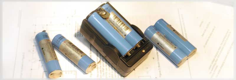
No need to be a genius to check the charging current. For a fully discharged battery It was low as 0.03A (top). And it's a good opportunity to see what is in the middle. Of course, I took off a plastic hood and got access to the board.
As you can see in the picture, the circuit is logically divided into two parts, by transformer. Left - AC-DC converter, on the right - the charging circuit w/LED.
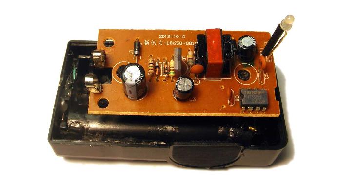
After a short research I found out that AC-DC converter does not supply enough power to the charging system. Transformer looked overheated, which indicated an internal short.
To check the charging circuit, which may be still alive, I powered it up by external 6 Volts (according to the datasheet top voltage is 8V) and completely burned the charger.
The rest was made just for fun. Namely, draw a schematic diagram to check how it works and see what can be done. Since the number of components is limited and each properly labeled, the drawing of schematic does not take a lot of time.
Schematic works in the following way.
- When power is supplied, transistor Q1 begins to open through R1.
- This creates a voltage across the secondary winding (10t), which further opens transistor Q1, through R3,C2.
- When the core is saturated, the transistor is OFF and all of the energy stored in the transformer's core charges capacitors C3,C4 and the cycle is repeated.
- Everything works this way until the voltage on the C3 reaches +0.7V-4.2V=-3.5V (4.9V on C4).
- Voltage on C3, greater than -3.5V, increases OFF time for Q1, because it takes time until C3 is discharged to -3.5V through R1 and makes it possible to open Q1 for the next cycle.
* In this way ZD1, C3 - works as simple PWM, and serves to stabilize the output voltage.
Rest of the schematic, stand alone charging circuit on HT5382, works as specified in the datasheet.
In my case, the problem was caused by incorrect Zener ZD1, which should have a voltage as 5.1V. This should raise the output voltage to approx. 6.2V and allow the charging circuit, on HT5382, to operate properly.
But it's too late for this charger...
The good side is that now I have a beautiful holder for two 18650 and I can make a new circuit, better and more reliable. In this case, Li-Ion Battery Charger on MSP430 (SLAA287) looks suitable.
27 july, 2016 SKootS