17. Simple electronic devices.
17.16 Motion Sensor LED Light.
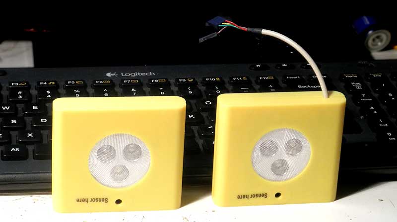
In this case, I was looking for cheap housing with space for 3 AA/AAA batteries. The idea was to find a place for my anemometer and controller (this one), which are, already a month, goes with me on my kayak as a board and sensor. Of course, it's covered with a conformation coating (1A33), but in the box it will looks much better.
Better solutions than 'Motion Sensor Light' from 'Dollar Store' I have not found. Place for 3 AAA batteries, and plenty of room for controller's board in a middle.
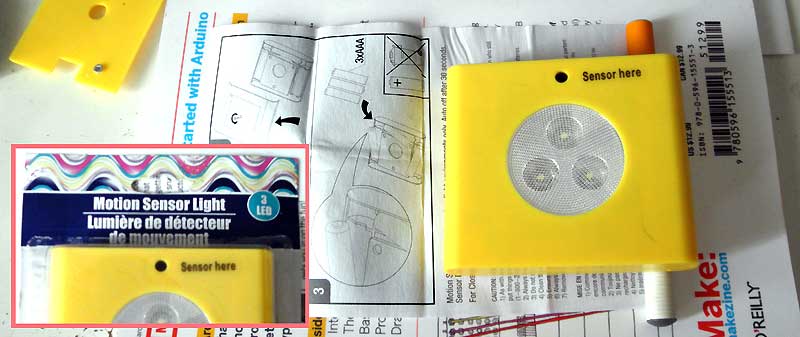
I have to say at first, that this device has exceeded all my expectations. Indeed, I expect to see cheep board with epoxy dot in the middle and a ton of wires flying around. And, it did not happen. But all in order.
The first surprise was when I installed three batteries and the device began to work properly. LEDs was turn ON for ~30 seconds, each time when I pass around.
There is no power switch on the device. So I decided to check the current consumption in standby mode. Schematic consume only 70 uA (0.07mA at 4.5V)! There was a second surprise. Perhaps it is only for me and I would like to explain why. I'm doing some small devices (on TI) that run for years and consume little power. Usually 300uA (0.3mA at 3V). Therefore, 70uA is much better than I expected.
In any case, when the light is ON, it consume about 75mA at 4.5V.
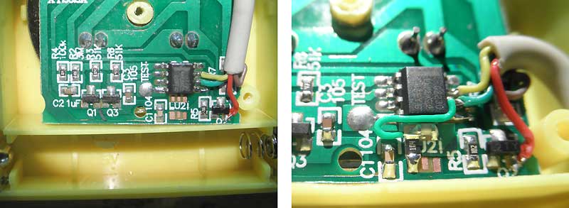
Of course, I took off a plastic hood and got access to the board. There was a last surprise. No wires and board made from the individual components.

The circuit diagram is very simple. Looks like everything is done according to "The Art of Electronics", P.Horowitz & W.Hill, 1980.
Hard to say what type of microcontrollers it. From inexpensive 8 pins microcontrollers direct match, for PIC12F1571/2. With minor modifications (switch output from pin 6 to pin 3 or 5), we can use MSP430G2210/2230.
Since the number of components is limited and each properly labeled, the drawing of schematic diagram does not take a lot of time.
Schematic works in the following way. Light sensor CDS (R1) powered through R4. As the light increases, it generates a small negative pulse, which is amplified by Q1,Q3. R4,C3 expands short pulses to 0.1 second. The microcontroller U1 receives this pulse on pin 2 and extends to 30 sec. on pin 6 (if 'TEST' connected to the GND - extends to 0.5sec. or less). Q2 - driver for LEDs. R5 - current limiter for Q2, R7 - for LEDs.
For me it was interesting to find out which microcontroller is there. The marking missing on the top. The bottom part of the chip, it is the place where real marking may be.
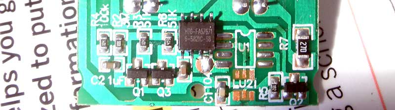
"HTG-FA57671 6-5821C-S8" - does not help at all. At least we know what's under the chip.
Now, when we already know the schematic ... It's hard to say why this circuit uses microcontroller. A simple modification allowing to easily get rid of it. Enough to connect capacitor C3 to base of Q1. It will turn Q1 & Q3 to monostable multivibrator, which with capacitor C3=47uF will do the same - long pulses, of about 30 seconds, at the output.
If I burn a microcontroller, then I will do so.
Plain design, nothing interesting.
In General, that's all we need to know to use this