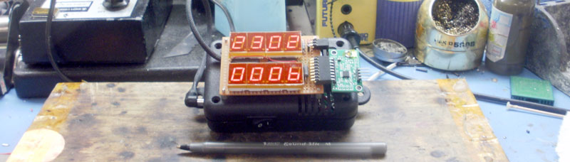
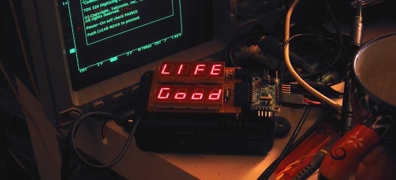
8 digits screen (two lines by 4) based on two SN74HC595N. Serial connection to MSP430 (data via 'Data' & 'Clock' lines).
Two chips 74HC595 and a set of 7-segment LEDs (plus a few hours of time) and an indicator, just like on a banner from above, ready to run (schematic here).
We will program MSP430 as a bridge between GM counter & screen. Why? Because :
1. MSP430 LaunchPad Development kit with two MC in addition, it is a ready to go programmer / debugger for any MSP430 and it starts to work "out of the box";
2. Everything that is necessary for work is downloaded from the TI website - for free;
3. The headphone output of GM counter is compatible with micro-controller's inputs.
4. The micro-controller has, however, low power consumption.
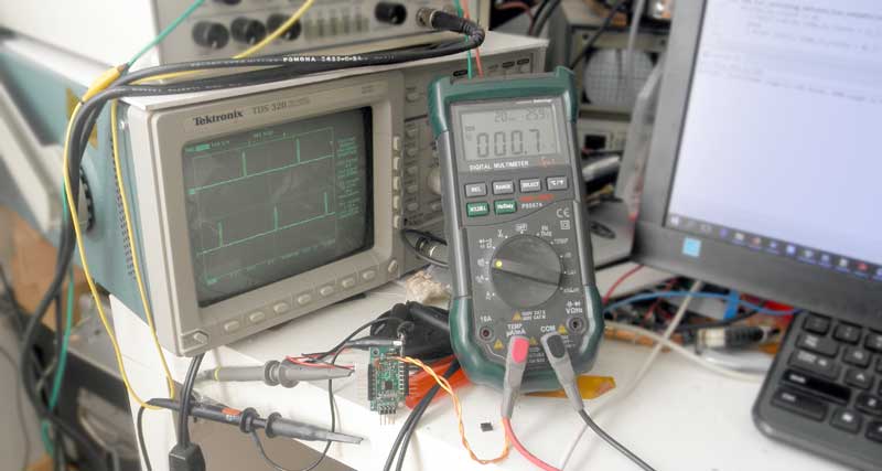
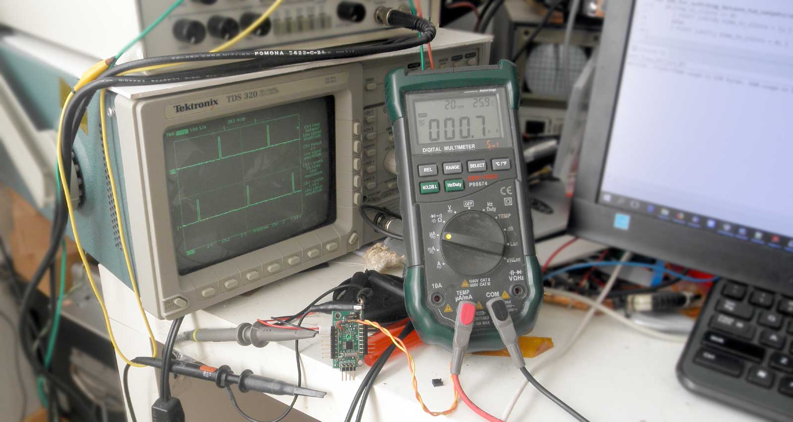
As an example of the latter, the next photo shows a generator for quartz clock, that forms pulses each second. Oscilloscope probes are disconnected, since they affect the total current consumption.
But let's leave the power consumption at rest.
To understand what we are talking about and what we are going to program, a simplified schematic diagram is very useful. MSP430 takes sound pulses (~1 millisecond) from 'Head phone connector' of GM counter and outputs the data to the screen via a serial (DATA+CLK).
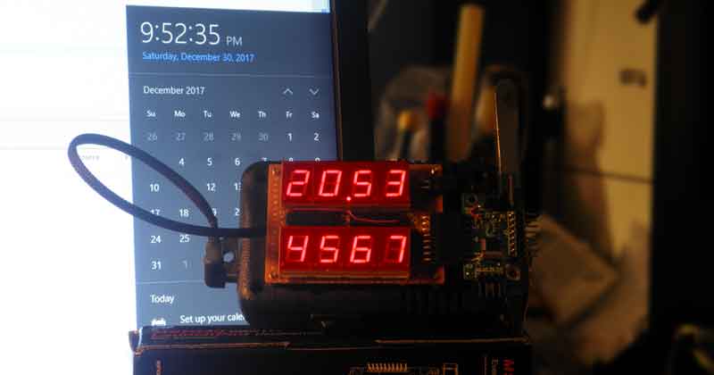
I like to send time (military format) to the top line of the screen and the radiation level (current number of pulses per minute) to the bottom.
It should be a small plan, before we start programming. If you have it, then you program the micro controller even without me. The plan will be as follows.
1. Run the micro controller from 32768 crystal, since we need the exact time.
2. Put the micro controller into sleep and wake up 512 times per second, to calculate the time.
3. Open additional buffer (for 8 digits), where store everything that will be displayed on the screen.
4. Convert current the time to numbers (LED's images) and update the buffer, every minute.
5. Sub-program will output the contents of the buffer to the screen (512 or ~1000 times per second).
*. From this moment, the clock and screen are already working.
6. Read the time (in 1/512 part) between pulses from GM counter, and store the last 16 values.
7. Recalculate the last 16 values to one - pulses per minute.
8. Update the second line in the buffer.
9. Done.
Configure the watch dog timer as a source of interrupts every 1/512 second and count time is the simplest part of the task. The next part will do parts 1, 2 and part of 4.
Now, we need to bring this to the screen. To do this, let's digress from programming and see how 74HC595 works.
74HC595 is a slightly more complicated version of 74HC273, where all 8 internal triggers are already connected in series. The input and control signals can be simplified to the next figure.
On the rising edge of CLOCK signal, the data from DATA input is written to the first trigger, and the signal that was on its output, before, is written to the next trigger in the chain. In the end, the 8 bits that we pushed into the chip appear sequentially on the outputs Q0 -Q7 on the front edge of the WRITE signal.
Already now, we can directly connect a seven-segment LED to the output of the 74HC595 and light up the characters we want.
Since the "common anode" is connected to the "+", the zeros at the output of the 74HC595 will light individual LEDs on '7 segment'. Therefore, the program adds one more stack of constants, with a hexadecimal representation of each digit.
The last line (5) is the buffer, for display on the indicator. The first half of the 16-bit variable is the digit (or lighted LEDs), the second is the position on the screen. From this "dim" the indicator's maintenance program will sequentially select the 'digits + position' and show on the screen ~512 times per second.
The following sequence on DATA, CLK & WRITE shows how to output the character "c" in the seventh position of the screen.
Again, nothing complicated. The low level at the output of the first 74HC595 and the high level at the output of the second 74HC595 - lights the LED.
It's very simple to write a small 7-LED service program. In general, there is nothing to write about. It's simple, if you approach it creatively ...
As expected, the program lights the number 3 in the first position of the screen.
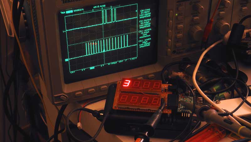
By the way, the first bit, which was sent into 74HC595, is on the 'scope screen' on the right ...
Now it's time to bring something to the screen. The inscription "Hello Word" will be displayed by Keegan and Ritchie. I would bring out the title of the song Despacito + Victoria’s Secret Show . But we will derive something simple, such as the improvised "Life is Good".
For me it is convenient to open a dim with 8 images, together with the position on the screen. 8 bits per image and 8 bits per position. Moreover, variables, by default - 16-bit. The additional counter "counter_for_screen_position" scrolls from 0 to 7 and selects the dim's element that is merged to the screen with the "push_16bit_to_display ()" subroutine.
/ * WDT is better to stop, since the "WDT Reset" gives an unpleasant flash on the screen. * /
It remains to change the status of the constant "Txt_on_screen_with_position [8] = {}" to a variable and put into upper bytes the images of numbers or letters to display. Speaking the right language, then use this variable as the "screen buffer".
The small problem is that the variables that accumulate time during the program (time count), are not related to the image on the screen.
To display the time on the screen, proceed as follows. We add time in hours multiplied by 100, with time in minutes. For 20 hours, 53 minutes is 2053. Find the remainder of dividing by 10. This will be the last digit - 3. Select the configuration of the LEDs from "dec_digit_to_7_segmentLED ()", which replaces the 4th variable in the "screen buffer" (only the high byte), divide 2053 by 10 and repeat for the numbers 3, 2 and 1.
In addition, in this routine:
line 10: restores the last byte - the position of the digit on the screen;
line 14: lights the "dot" between the hours and minutes (line 14);
line 17: extinguishes "0" in the first position (line 17) if it is not needed.
And, on the screen, it looks very good.
It works and the rest you can do yourself. Just like the last time, the coding is 'straight ahead' and does not take much time. Of course, you will do it sooner than I do.
A few reminders that are perhaps important.
As before, the screen's update falls on the shoulders of MSP430. The micro controller does this job nonstop, 512 times per second (each digit is updated 64 tps). To do this simply way, MSP430 runs from 32768 crystal (X1) and the WD Timer awakens processor, precisely, each 1/512 sec.
Coding for SN74HC595 is simple, too. The positive edge on a 'clock' line writes the status of 'data' line to the first trigger. The positive edge on a 'write' - overwrite output. One digit is shown at one time.
Most likely, my final version of software will be on the next page.
/* P.S. My code is already written and working : ) But it is far from perfect, and not ready to be shown here. */
For me, only: static image on the screen (0.014 + 1536);
MSP430. 7-segment LED and old GM counter.
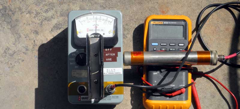
Some time ago, I got an old GM counter in my hand. After some magic with the soldering iron, I turn it into a reliable tool that can work continuously for about a year, from one set of batteries.
And it works on the floor, in the basement. But to read the data from it is a bit inconvenient. A simple solution is to send the data to a 7-segment LED, which can be located anywhere.
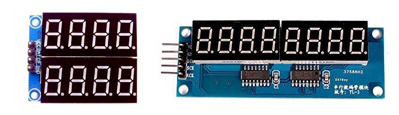
As a screen, I could buy something similar to this, but wait a few weeks ... I do not like it.
Two chips 74HC595 and a set of 7-segment LEDs (plus a few hours of time) and an indicator, just like on a banner from above, ready to run (schematic here).
We will program MSP430 as a bridge between GM counter & screen. Why? Because :
1. MSP430 LaunchPad Development kit with two MC in addition, it is a ready to go programmer / debugger for any MSP430 and it starts to work "out of the box";
2. Everything that is necessary for work is downloaded from the TI website - for free;
3. The headphone output of GM counter is compatible with micro-controller's inputs.
4. The micro-controller has, however, low power consumption.
As an example of the latter, the next photo shows a generator for quartz clock, that forms pulses each second. Oscilloscope probes are disconnected, since they affect the total current consumption.
But let's leave the power consumption at rest.
To understand what we are talking about and what we are going to program, a simplified schematic diagram is very useful. MSP430 takes sound pulses (~1 millisecond) from 'Head phone connector' of GM counter and outputs the data to the screen via a serial (DATA+CLK).
I like to send time (military format) to the top line of the screen and the radiation level (current number of pulses per minute) to the bottom.
It should be a small plan, before we start programming. If you have it, then you program the micro controller even without me. The plan will be as follows.
1. Run the micro controller from 32768 crystal, since we need the exact time.
2. Put the micro controller into sleep and wake up 512 times per second, to calculate the time.
3. Open additional buffer (for 8 digits), where store everything that will be displayed on the screen.
4. Convert current the time to numbers (LED's images) and update the buffer, every minute.
5. Sub-program will output the contents of the buffer to the screen (512 or ~1000 times per second).
*. From this moment, the clock and screen are already working.
6. Read the time (in 1/512 part) between pulses from GM counter, and store the last 16 values.
7. Recalculate the last 16 values to one - pulses per minute.
8. Update the second line in the buffer.
9. Done.
Configure the watch dog timer as a source of interrupts every 1/512 second and count time is the simplest part of the task. The next part will do parts 1, 2 and part of 4.
Now, we need to bring this to the screen. To do this, let's digress from programming and see how 74HC595 works.
74HC595 is a slightly more complicated version of 74HC273, where all 8 internal triggers are already connected in series. The input and control signals can be simplified to the next figure.
On the rising edge of CLOCK signal, the data from DATA input is written to the first trigger, and the signal that was on its output, before, is written to the next trigger in the chain. In the end, the 8 bits that we pushed into the chip appear sequentially on the outputs Q0 -Q7 on the front edge of the WRITE signal.
Already now, we can directly connect a seven-segment LED to the output of the 74HC595 and light up the characters we want.
Since the "common anode" is connected to the "+", the zeros at the output of the 74HC595 will light individual LEDs on '7 segment'. Therefore, the program adds one more stack of constants, with a hexadecimal representation of each digit.
The last line (5) is the buffer, for display on the indicator. The first half of the 16-bit variable is the digit (or lighted LEDs), the second is the position on the screen. From this "dim" the indicator's maintenance program will sequentially select the 'digits + position' and show on the screen ~512 times per second.
The following sequence on DATA, CLK & WRITE shows how to output the character "c" in the seventh position of the screen.
It's very simple to write a small 7-LED service program. In general, there is nothing to write about. It's simple, if you approach it creatively ...
As expected, the program lights the number 3 in the first position of the screen.
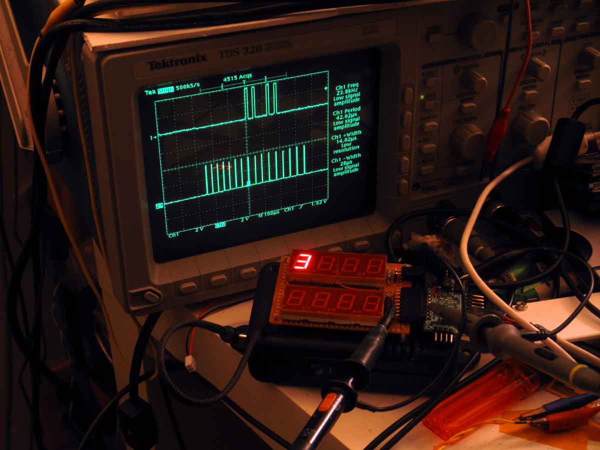
By the way, the first bit, which was sent into 74HC595, is on the 'scope screen' on the right ...
Now it's time to bring something to the screen. The inscription "Hello Word" will be displayed by Keegan and Ritchie. I would bring out the title of the song Despacito + Victoria’s Secret Show . But we will derive something simple, such as the improvised "Life is Good".
For me it is convenient to open a dim with 8 images, together with the position on the screen. 8 bits per image and 8 bits per position. Moreover, variables, by default - 16-bit. The additional counter "counter_for_screen_position" scrolls from 0 to 7 and selects the dim's element that is merged to the screen with the "push_16bit_to_display ()" subroutine.
/ * WDT is better to stop, since the "WDT Reset" gives an unpleasant flash on the screen. * /
It remains to change the status of the constant "Txt_on_screen_with_position [8] = {}" to a variable and put into upper bytes the images of numbers or letters to display. Speaking the right language, then use this variable as the "screen buffer".
The small problem is that the variables that accumulate time during the program (time count), are not related to the image on the screen.
To display the time on the screen, proceed as follows. We add time in hours multiplied by 100, with time in minutes. For 20 hours, 53 minutes is 2053. Find the remainder of dividing by 10. This will be the last digit - 3. Select the configuration of the LEDs from "dec_digit_to_7_segmentLED ()", which replaces the 4th variable in the "screen buffer" (only the high byte), divide 2053 by 10 and repeat for the numbers 3, 2 and 1.
In addition, in this routine:
line 10: restores the last byte - the position of the digit on the screen;
line 14: lights the "dot" between the hours and minutes (line 14);
line 17: extinguishes "0" in the first position (line 17) if it is not needed.
And, on the screen, it looks very good.
It works and the rest you can do yourself. Just like the last time, the coding is 'straight ahead' and does not take much time. Of course, you will do it sooner than I do.
A few reminders that are perhaps important.
As before, the screen's update falls on the shoulders of MSP430. The micro controller does this job nonstop, 512 times per second (each digit is updated 64 tps). To do this simply way, MSP430 runs from 32768 crystal (X1) and the WD Timer awakens processor, precisely, each 1/512 sec.
Coding for SN74HC595 is simple, too. The positive edge on a 'clock' line writes the status of 'data' line to the first trigger. The positive edge on a 'write' - overwrite output. One digit is shown at one time.
Most likely, my final version of software will be on the next page.
/* P.S. My code is already written and working : ) But it is far from perfect, and not ready to be shown here. */
For me, only: static image on the screen (0.014 + 1536);