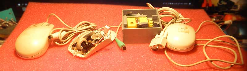
I'm just thinking about re-using things.
Reverse engineering for PS2 mouse (Logitech).
I can assume that you are going to use the encoders from the old PS2 mouse, for the Arduino project. My project is for MSP430, but it does not matter. This is possible, although not as simple as it seems.
What you should know in the beginning: the maximum, reliable, rotation speed for this design is, approximately, 3600 rpm, for encoder's wheel with 65 holes, and 4800 rpm for 48.
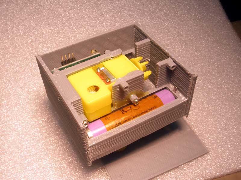
The main idea was to use sensors from PS2 mouse for for tracking the speed of the electric motor. A device for tracking sun light, on the right, for example only.
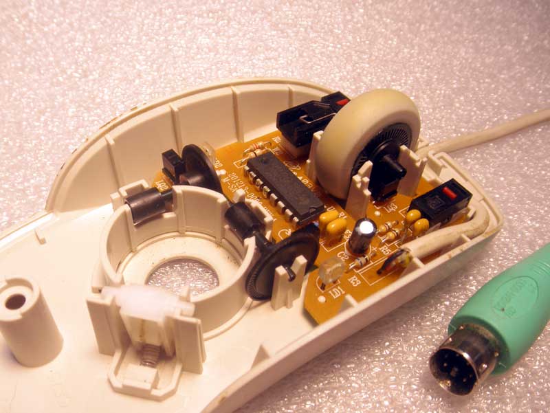
The short way is to figure out how the sensors works is to take schematic first. It's simple, and it does not take more than 10 minutes.
Pin out of PS2 complements the schematics, and the number of holes in the encoder's disks is good to know for future calculations.
More pictures, I put on another page. If you need, you can see them here.
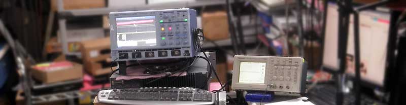
And this is where fun begins. Any oscilloscope will be good. Small Tektronix, just because it's easier to work with.
First of all, we disconnect a one sensor (LQ1) and see what signals the controller (U1) generates.
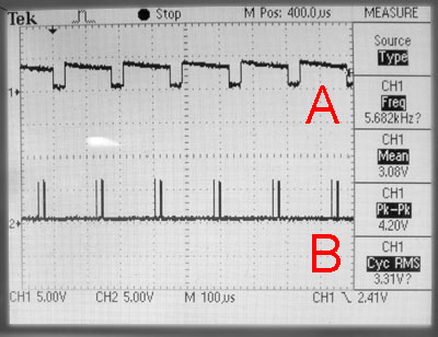
As we can see, the microcontroller lights IR LED every 175 microseconds, After that, after about 100 microseconds, it sends two short pulses to the sensor. All these pulses are always the same.
Nothing will change if we attach the sensor LQ1 back to pin 11.
This will be so until we turn the encoder's wheel. If the holes in the wheel are moved upward relative to the sensor, the sensor will add an additional pulse after the first pulse. If down, the same will be added after the second pulse generated by the controller.
To be more precise, after any movement, the sensor switches the output high (respectively after the first or second pulse) and the follow-up pulse from the micro controller resets this state to low.
Actually, that's all you need to know to use these sensors together with Arduino, MSP430, PIC16 or any other micro controller. They can have different markings, ...
... but as long as they have power, ground and one output, they work the same way as described.
The same, only a little deeper.
The time intervals, for LEDs (left) and sensors (right), are below. All the data on the oscillograms are real and you can count them, if necessary.
The following is for illustration only how the sensor responds if there was a move up (left osc.) and down (right).
Controller, lights the LEDs (LD1,2,3) simultaneously (p. A1,2), which is understandable from schematic diagram. He also polls all sensors (LQ1,2,3) at one time (p. B1,2,3). Signals sent along dd and oo are the same. The response of the sensors can be different, depending on the movement of encoder's wheels. And 'max' current consumption @5V, on the right.
As an addition:
- The polling time of the sensors is not stable, and can be in the range of 150-200 microseconds.
- The average current consumed by the LEDs 2.6mA & 4.6mA, & sensors - 0.01mA.
- The minimum voltage, at which the mice is still alive, is 3.6V.
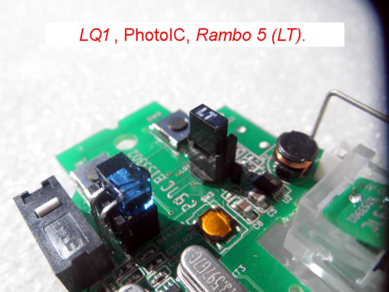
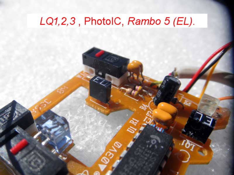
/* And now, do not make the simple mistake I made, in the beginning. In this position (pic.left) the sensor, the same will work, but not as you think.
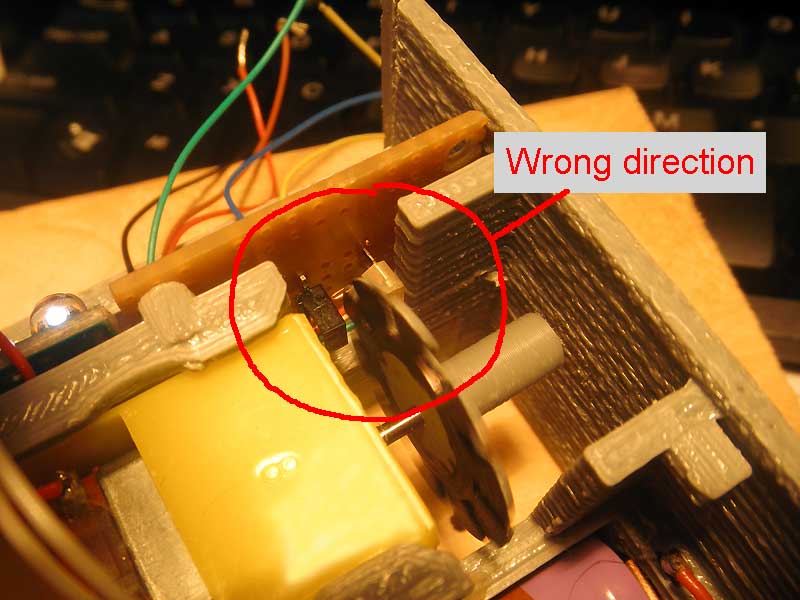
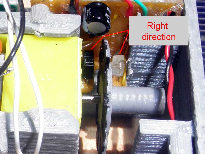
Of course, should be rotated by 90 degrees, as on the right photo. */
That's all you need to know. From this point of view, you can use this, for your applications.
*** This will work with MSP430F2012, and how it works in real life will be here (not ready yet). ***
*** And, if you find inaccuracies, or have something to add, then my address is lower.