
We do it for fun, and to save our time.
5.8.9 Coil Inter-turn Short-Circuit Indicator.
In the field of electronic equipment repair, the ability to quickly and accurately diagnose and fix problems is essential. One common issue that can occur in coils is an inter-turn short-circuit, which can cause a variety of problems, including reduced efficiency, overheating, and even complete failure of the equipment. To detect inter-turn short-circuits, a specialized tool known as a "Coil Inter-turn Short-Circuit Tester" is required. A simplified version, namely the "Short-circuited coil indicator" was made and tested.
This device is designed to detect any short circuits in various types of transformers onboard. Of course, if a short circuit is found, then the transformer must be disconnected and checked again, since the source of the short circuit may be on the board, and not in the transformer.
On the practical side, the device works very simply.
You connect two test leads to either winding of the transformer. When there is a connection, the red LED lights up. Further, if there is no short circuit in any winding, then the green LED lights up. If there is a short circuit, then the green LED will not light.
In the photo, a short circuit in one of the windings is simulated by a alligator clip.
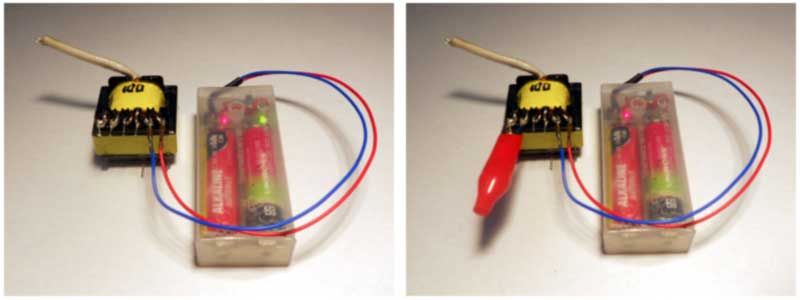
In short. The RED LED indicates connection, the GREEN LED that the transformer has no problem.
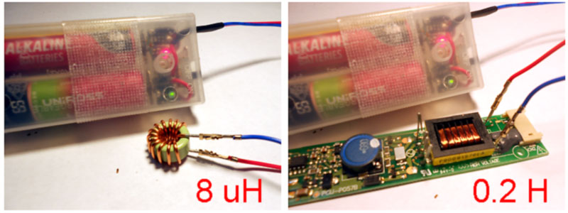
The device will cover a range from 8 uH (choke) to 0.2 H (Fly Back Transformer, output winding).
And the circuit diagram (for which you probably came) which was developed and works in this particular device. All the necessary information, to repeat a similar device, is already on the diagram (click to download picture, .gif file).

If you decide to finish reading here, then pay attention to the fact that there are two different "Grounds" in the circuit. This is done so that the device does not consume power if the coil is not connected and does not drain the batteries if you forget it turned "ON", on your workbench.
How it works and why.
The circuit is designed on the assumption that if there is a short-circuited turn in the coil, then it loses its inductive properties. Accordingly, in a simple oscillator, where inductive properties are required, it cannot work.
The oscillator circuit with positive feedback through a capacitor divider (Colpitts oscillator or so) was chosen, not because it is somehow good, but because it is possible to supply power to the circuit through an inductor.
Thus, the schematic diagram is divided into three parts: oscillator, coil connection indicator, oscillation detector. To make a long story short, these parts are colored in the following schematic diagram.
The "oscillator", on transistor Q1, will work with just about any inductance you find on the table. Unless the inductor has shorted turns or leakage, of course. The "connection indicator" looks at the voltage on the collector Q1. If the inductance is connected, a voltage appears there, opens the transistor Q2, the LED1 (red) lights up. At the same time, this allows the detector to work, since the drain, of the transistor Q2, appears low. In the "oscillation detector", the alternating voltage taken from emitter Q1 is amplified by transistor Q3, is detected (by D1, D2), turns transistor Q4 ON and LED2 (green) lights up. And, of course, if the oscillator is not working, then this does not happen, green LED2 will be OFF.
How it works in "on-line" circuit simulator, you can see here: https://tinyurl.com/2zlyvlqc
Since this is a quick project (2 days), the PCB was not developed. Everything just fell into place on the universal board, as you can see from the next photo. This is exactly what it looks like in real life.

The funny thing is that it works great.
The last thing I would like to say is that this circuit is designed for a battery supply voltage of > 3 Volts. Therefore, from nickel-cadmium rechargeable batteries, which give 2x1.2V=2.4 Volts, the circuit must be changed. Although from three kind of rechargeable connected in series (3.6V), this will work even better.
I plan to simplify and improve this device. If you have any questions then let me know.