10. Any repairs yourself, including radios..
10.2 A good radio Sony ICF-2010, a standard problem.
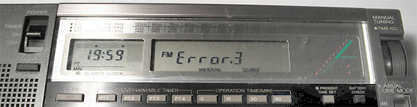
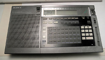
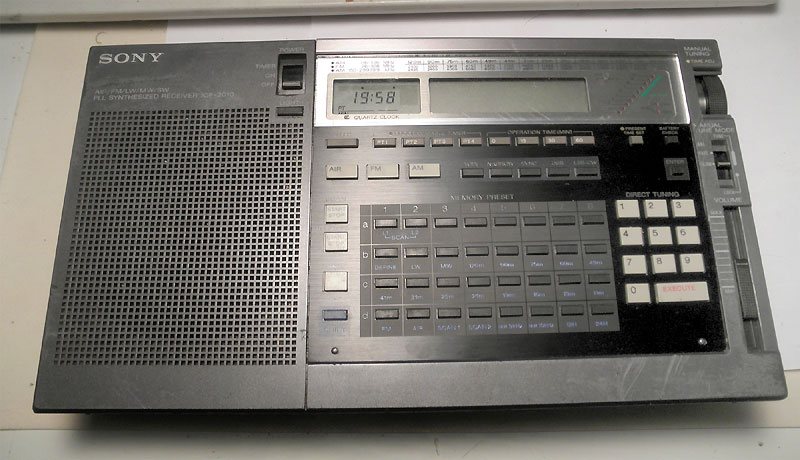
It's about radio, Sony ICF-2010. It is, of course, 1985 release. Now - 2012, or even 2017, and it finally (after 27 years:) stopped working. After turning on, the screen shows "ERROR.3" and silence...
 And, if you have a similar problem, then I want to congratulate you. Firstly, you hold in your hands one of the best radio ever made.
As I know? In life I am engaged in electronics repair and many things passed through my hands. And, in my experience, this radio - the BEST OF THE BEST!
The second news, the same good. If you kill this radio or, for some reason, you can not repair it, by yourself, then I will do it for you. You will need to figure out how to send it to Boston, MA. I will take care of the rest.
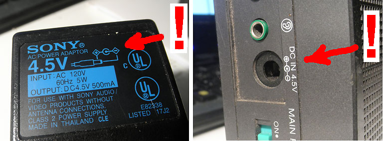
It's very easy to kill if you do not pay attention to detail. You probably do not have an original power supply for this radio and hardly noticed that the power plug has a reverse polarity, which almost does not occur at the moment. 12V power supply with wrong polarity will kill it, for sure. The correct power supply in the photo.
The statement, which was downloaded from the Web site Sony, specifically said that "ERROR.3" - this is a problem with power, and nothing more. Batteries, external power supply - it does not matter. The main thing that is not part of the processor board.
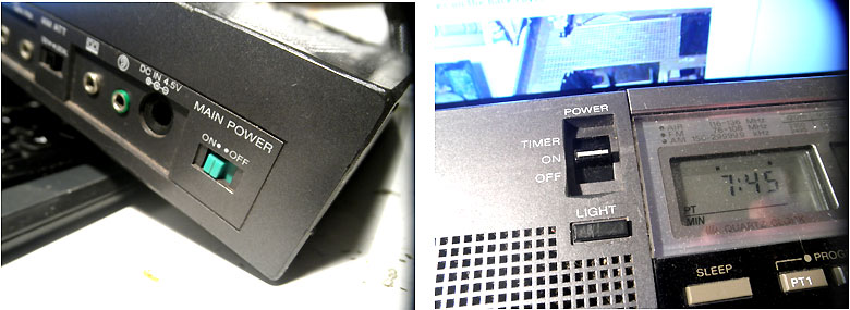
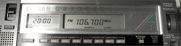
If this is your lucky day, then install new batteries (2xAA, 3xD size) and turn both switches ON as in the photo. And enjoy working radio.
If nothing has happened, and you continue to have an 'Error.3', you can move on.
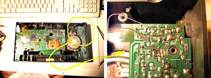
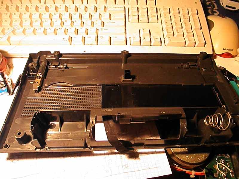
In short, the problem with the battery unit. It is located in the back cover and connects to the motherboard using the contacts. No wires on the back cover of the printed circuit board is provided.
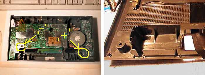
On the left picture a place where connecting the positive and negative contact of the battery compartment. On the right - a place where there was a positive contact spring (visible in the next photo).
Time, of course, has its. Plastic deformed and positive contact the battery compartment lost connection to the board .
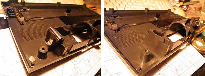
The problem is clear. How to repair each chooses. Heat the plastic materials and level (glue) does not pass for an old plastic. It will crack somewhere else. And it will look - not good. It would be possible to add connection with conventional wires. This simple solution will work, but I do not like it. I installed an additional "clip" that clings to the edge of the plastic and makes the plastic wall flat. It takes time, but looks very good as the original.
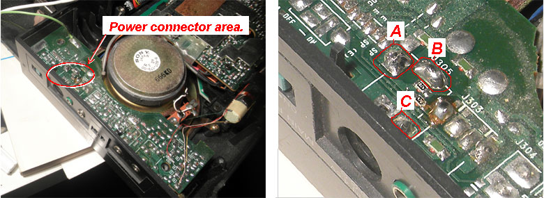
Another, easily to fix problem may occur under the power connector. Be sure that the solder joints on the board looks good, without cracks or corrosion (broken traces, on the board, are the same). Move power socket slightly with your finger. This illuminates the problem. Even if they looks good, it makes sense to re-solder them with one touch of the soldering iron. If you do this, then lift the board up a little, so as not to damage the plastic's corner with heat.
* On the last picture of the battery compartment already connected to the board using additional wires.
Nothing more. Tighten 6 screws and enjoy your radio.
The following is optional if you want to have a radio as good as new or even better.
First, it is necessary to clean the dust from everywhere, and the speaker from the metal sawdust, which is unknown how appear inside, on the magnet. It will return a clear sound and beautiful appearance.
Second, I'm pretty sure that a few buttons do not work. You can live with this, but it can be easily fixed.
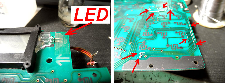
Third and last. You probably noticed that the backlight of the LCD screen, a little dull. Green LEDs, 25 years old, do not produce enough light. If you have already dismantled this radio, then it makes sense to change them to white LEDs. The latter can be extracted from the solar garden lantern, bought in a "Dollar Store". This works more than well.
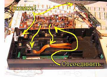
OK. If you want to disassemble this radio, then you need to know that without a soldering it can not be done. There are no connectors (other than flexible cables to the CPU unit). Therefore, necessary unsolder magnetic antenna and a speaker wires.
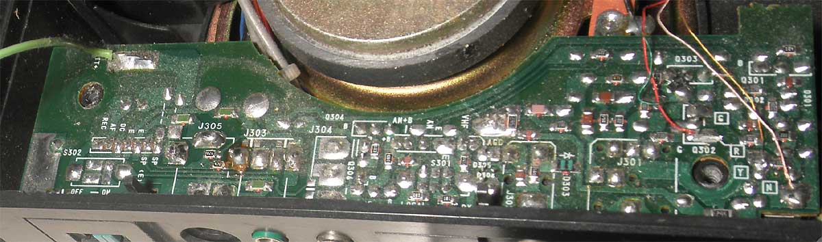
The right picture can help to solder the wires of the magnetic antenna in its place. Although they signed on the board.
My mistake was that I wanted to do everything, "Quick," and in the beginning did not unsolder the wires from the magnetic antenna. But I quickly corrected.
Unscrewing the three screws, you can raise the RF board. Carefully, because it connected two loops on the processor side. After a recent trip, you need to unsolder the three wires going to the "variable capacitor". In quotes, because it is an encoder, which transmits the signal to processor (the position of the tuning knob).
There is one unpleasant moment - the wires coming from the radio frequency board to the indicator board.
 This wire without connectors, but long enough. Before you raise the CPU board, it must be carefully straightened.
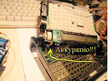
Then you can gradually remove the motherboard from the case, constantly pushing this cable in the gap.
As soon as enough space - unscrew one screw on the indicator board and remove it.
* The speaker is better to remove too. It is a good idea to clean it (the front portion of the cone and the outer side of the magnet). This is easily done by using chewing gum :)
Here, simple work ends. In order to replace the green LED, it is necessary to raise the bezel of the LCD screen. This can be done, but takes a little time.
If, by this time, your enthusiasm has not dried up, you can try to restore the disabled buttons. I will say that rubbing everything with alcohol - does not work. The problem are in VIA and traces on the keyboard that need to be restored. This requires good friendship with the soldering iron, as well as with multi meter, and if you never did, then it's best to consult those who know how to do it correctly.
And, I would advise you to make a list of buttons that do not work or work badly, before you start to disassemble the radio. This will save you a few hours.
Finally, after 4 hours of work, we have the result. It looks like this.
The dark places on the board are where the tracks were restored. After that, they are washed with alcohol and covered with a protective coating. In this case, with transparent nail polish.
That's all. Gather it all together and enjoy a good radio from the last century.
Do carefully and you will be successful !
*** Of course, it good to have disassembly photos. Step by step. The value of the past begin to think in the process of assembly :)
Just in case.
The circuit schematics of this radio (Sony ICF-2001D, ICF-2010) is on eserviceinfo.com. If it has moved out, which usually happens, then download its saved copy (.gif, 4.6M).
AND ...
And, when everything is finished and working, compare Sony's sensitivity to the modern software radio.
They do not even stand close. This will show you that the work, you just did, makes a sense.
Addition.
And in the end, a photo that is completely unrelated to this radio. It just reminds me that we do many things for pleasure & fun. Including photographing nature.
I do not know about you, but it seems to me that the frog is simply beautiful :)
Good luck.
If you find 499 $ in 90's to buy this radio, you will be able to repair it, by yourself! Do everything slowly and carefully.
It's about radio, Sony ICF-2010. It is, of course, 1985 release. Now - 2012, or even 2017, and it finally (after 27 years:) stopped working. After turning on, the screen shows "ERROR.3" and silence...
 And, if you have a similar problem, then I want to congratulate you. Firstly, you hold in your hands one of the best radio ever made.
 As I know? In life I am engaged in electronics repair and many things passed through my hands. And, in my experience, this radio - the BEST OF THE BEST!
The second news, the same good. If you kill this radio or, for some reason, you can not repair it, by yourself, then I will do it for you. You will need to figure out how to send it to Boston, MA. I will take care of the rest.
It's very easy to kill if you do not pay attention to detail. You probably do not have an original power supply for this radio and hardly noticed that the power plug has a reverse polarity, which almost does not occur at the moment. 12V power supply with wrong polarity will kill it, for sure. The correct power supply in the photo.
The statement, which was downloaded from the Web site Sony, specifically said that "ERROR.3" - this is a problem with power, and nothing more. Batteries, external power supply - it does not matter. The main thing that is not part of the processor board.
If this is your lucky day, then install new batteries (2xAA, 3xD size) and turn both switches ON as in the photo. And enjoy working radio.
If nothing has happened, and you continue to have an 'Error.3', you can move on.
In short, the problem with the battery unit. It is located in the back cover and connects to the motherboard using the contacts. No wires on the back cover of the printed circuit board is provided.
On the left picture a place where connecting the positive and negative contact of the battery compartment. On the right - a place where there was a positive contact spring (visible in the next photo).
Time, of course, has its. Plastic deformed and positive contact the battery compartment lost connection to the board .
The problem is clear. How to repair each chooses. Heat the plastic materials and level (glue) does not pass for an old plastic. It will crack somewhere else. And it will look - not good. It would be possible to add connection with conventional wires. This simple solution will work, but I do not like it. I installed an additional "clip" that clings to the edge of the plastic and makes the plastic wall flat. It takes time, but looks very good as the original.
Another, easily to fix problem may occur under the power connector. Be sure that the solder joints on the board looks good, without cracks or corrosion (broken traces, on the board, are the same). Move power socket slightly with your finger. This illuminates the problem. Even if they looks good, it makes sense to re-solder them with one touch of the soldering iron. If you do this, then lift the board up a little, so as not to damage the plastic's corner with heat.
* On the last picture of the battery compartment already connected to the board using additional wires.
Nothing more. Tighten 6 screws and enjoy your radio.
The following is optional if you want to have a radio as good as new or even better.
First, it is necessary to clean the dust from everywhere, and the speaker from the metal sawdust, which is unknown how appear inside, on the magnet. It will return a clear sound and beautiful appearance.
Second, I'm pretty sure that a few buttons do not work. You can live with this, but it can be easily fixed.
Third and last. You probably noticed that the backlight of the LCD screen, a little dull. Green LEDs, 25 years old, do not produce enough light. If you have already dismantled this radio, then it makes sense to change them to white LEDs. The latter can be extracted from the solar garden lantern, bought in a "Dollar Store". This works more than well.
OK. If you want to disassemble this radio, then you need to know that without a soldering it can not be done. There are no connectors (other than flexible cables to the CPU unit). Therefore, necessary unsolder magnetic antenna and a speaker wires.
The right picture can help to solder the wires of the magnetic antenna in its place. Although they signed on the board.
My mistake was that I wanted to do everything, "Quick," and in the beginning did not unsolder the wires from the magnetic antenna. But I quickly corrected.
Unscrewing the three screws, you can raise the RF board. Carefully, because it connected two loops on the processor side. After a recent trip, you need to unsolder the three wires going to the "variable capacitor". In quotes, because it is an encoder, which transmits the signal to processor (the position of the tuning knob).
There is one unpleasant moment - the wires coming from the radio frequency board to the indicator board.
This wire without connectors, but long enough. Before you raise the CPU board, it must be carefully straightened.Then you can gradually remove the motherboard from the case, constantly pushing this cable in the gap.
As soon as enough space - unscrew one screw on the indicator board and remove it.
* The speaker is better to remove too. It is a good idea to clean it (the front portion of the cone and the outer side of the magnet). This is easily done by using chewing gum :)
Here, simple work ends. In order to replace the green LED, it is necessary to raise the bezel of the LCD screen. This can be done, but takes a little time.
If, by this time, your enthusiasm has not dried up, you can try to restore the disabled buttons. I will say that rubbing everything with alcohol - does not work. The problem are in VIA and traces on the keyboard that need to be restored. This requires good friendship with the soldering iron, as well as with multi meter, and if you never did, then it's best to consult those who know how to do it correctly.
And, I would advise you to make a list of buttons that do not work or work badly, before you start to disassemble the radio. This will save you a few hours.
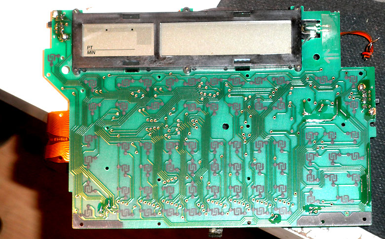
Finally, after 4 hours of work, we have the result. It looks like this.
The dark places on the board are where the tracks were restored. After that, they are washed with alcohol and covered with a protective coating. In this case, with transparent nail polish.
That's all. Gather it all together and enjoy a good radio from the last century.
Do carefully and you will be successful !
*** Of course, it good to have disassembly photos. Step by step. The value of the past begin to think in the process of assembly :)
Just in case.
The circuit schematics of this radio (Sony ICF-2001D, ICF-2010) is on eserviceinfo.com. If it has moved out, which usually happens, then download its saved copy (.gif, 4.6M).
AND ...
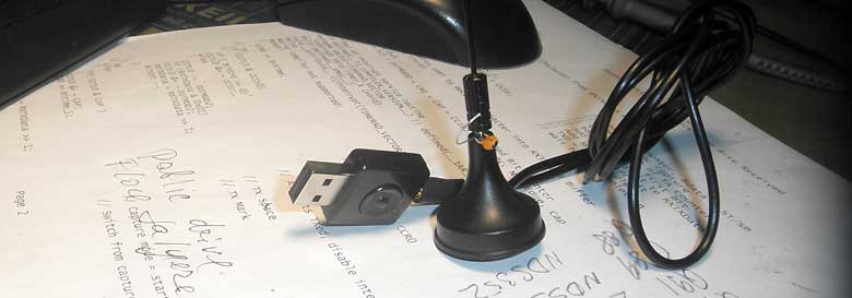
And, when everything is finished and working, compare Sony's sensitivity to the modern software radio.
They do not even stand close. This will show you that the work, you just did, makes a sense.
Addition.
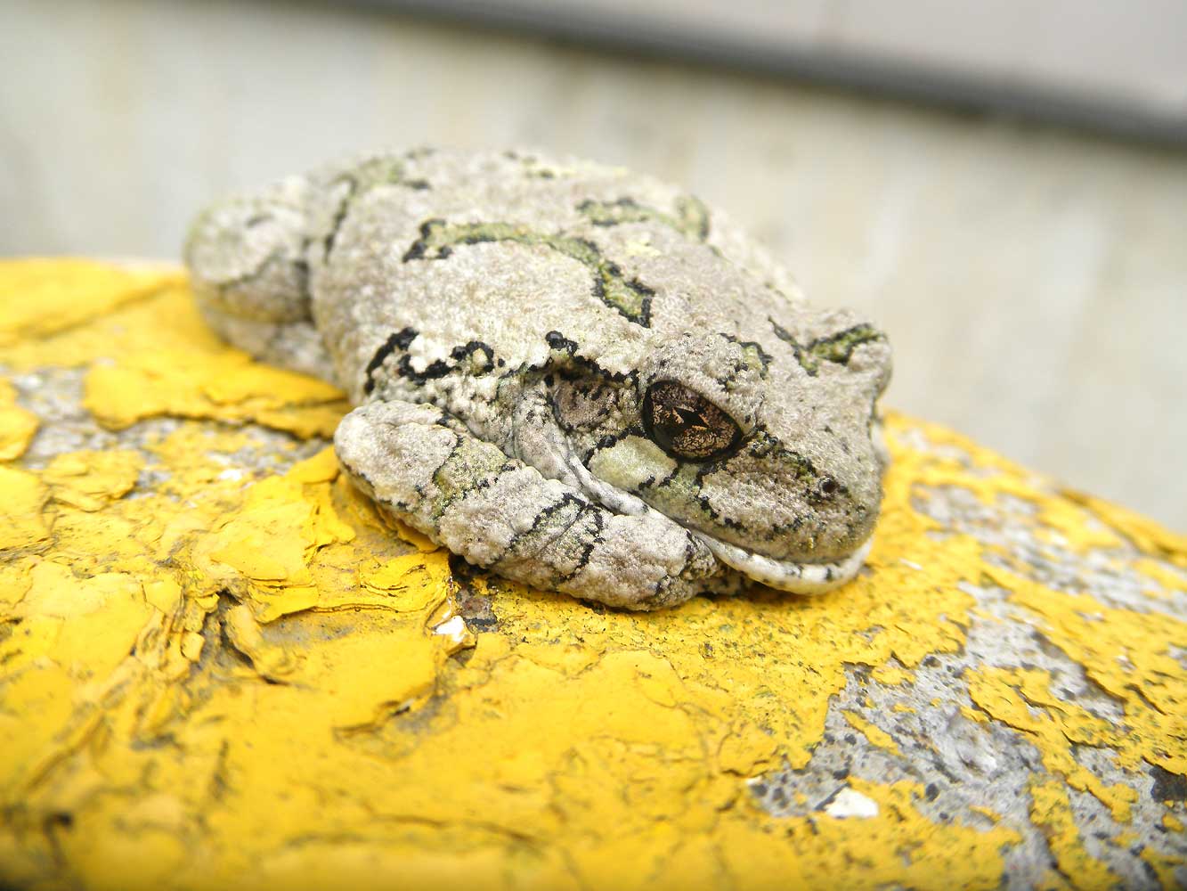
And in the end, a photo that is completely unrelated to this radio. It just reminds me that we do many things for pleasure & fun. Including photographing nature.
I do not know about you, but it seems to me that the frog is simply beautiful :)
Good luck.