The basic schematic.
We do a lot of different magic with electronics. And very often it is very simple things. In this case, I needed to light a small fluorescent tube, which requires about 1000 volts to start and 300 volts, to continue.
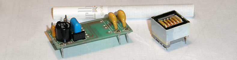
It's simple, and how it turned out, you can see on the picture.

Using a transformer and 2 transistors, the circuit is capable of generating 1000VAC (or little more) from a low voltage DC source (12VDC). From the schematic below, it doesn't get much simpler.
Before copying or modification just remember that the circuit produces enough power that would kill a small animal like a mouse or a cat. Be careful.
The rest is simple. L1 - reduces interference and AC current limiter for one time, R1 - BIAS for Q1 & Q2, C1 - absorbs voltage surges on collectors of both transistors, C2,C3 - current limiters for lights FL1 & FL2. In addition, the capacitor С1 and inductance of T1 (winding 1 & 2) form a resonant circuit. It forced converter to work at the fixed frequency, about 40kHz.
What happens in the circuit.
The oscilloscope is a device which is very helpful in this case. It is enough to know what is happening at L1 (right side) and collectors of transistors to make assumptions.
And if you think you know how this simple circuit works, then hold your breath ... You'll be surprised.
Inductance L1 together with the capacitor C1 and inductance of the transformer windings 1 & 2 form a complex resonant circuit, which increases the voltage on the transformer. For a classical converter circuit (without inductance L1) this voltage will be not greater then supply voltage (10 Volts, in this case).
Of course you might expect the oscilloscope mistake, but the other showed the same picture.
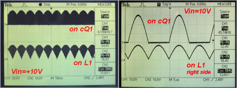
For me it is not so important what is happening in the circuit, such as that, transformer output (winding "4") will have the same voltage as on winding 1 or 2, multiplied by 73 (950t/13t). For this example, when Vin=10V, the voltage across the primary winding ~ 32 Volts, Vout=73*32V(max)=2336V(max) or *1.41=1656VAC.
In general, it good to convert 10VDC to 1600VAC, for such a simple converter.
Force input voltage to the limit.
Since the circuit is already running, it is interesting to know what the maximum voltage it will take. To do this, enough to measure the current consumption without load for different input voltages (FL1 & FL2 disconnected).
Actually, we are pushing our luck here. In accordance with wave-forms, maximum voltage for transistors (for 2SC4487 it is +60V) has been exceeded at a supply voltage Vin=18V. This is the theoretical limit for this circuit with transistors 2SC4487.
Output AC voltage vs. input DC.
We are experiencing difficulties with measuring the voltage greater than 1000 volts. When it comes to AC HI voltage at 40kHz, the difficulties even more.
On the other hand, the measurement of high voltage do not necessarily to do directly. For this circuit the output voltage depends on the voltage across the primary winding, and the latter depends on the power supply voltage. Thus, it is necessary to know the coefficient of proportionality between input DC voltage (Vin) and output AC (Vout).
This can easily be done with an oscilloscope, at low input voltages, when Vout < 250VAC. In next graph, the colored lines are terminated when the V(out) has reached oscilloscope limit. The rest are calculated (thin lines).
In this case, the voltage on the graph is slightly less than expected. This is due the fact that the oscilloscope, which was connected to the output, has an input impedance (10MOhms), which was a 'load' for converter. Besides, my probe has a limit - 600V (Vp-p) at 1/10.
What to do next.
If we already have a high-voltage source, it is logical to increase the output voltage even more. If we add to the circuit voltage multiplier we can get some fun.
With a sharp needle and a small metal ring it easy can become an 'ozone generator'. About it on the next page.