
The basic.
We love yagi antennas. They are simple and work by default and correspond well with the calculations. When we buy it, we hope that someone made these calculations for us and did it for less then $10, shipping included. It was always a good idea to check this.
I decided to check it, because the money is less than the cost of the materials needed to manufacture it. And got it home, well packaged, as promised. No complaints at all.
If we look in more detail, the only problem will be that the second element is a bit out of position. It does not matter, and easy to fix. Friction under all elements are good, nothing loose.

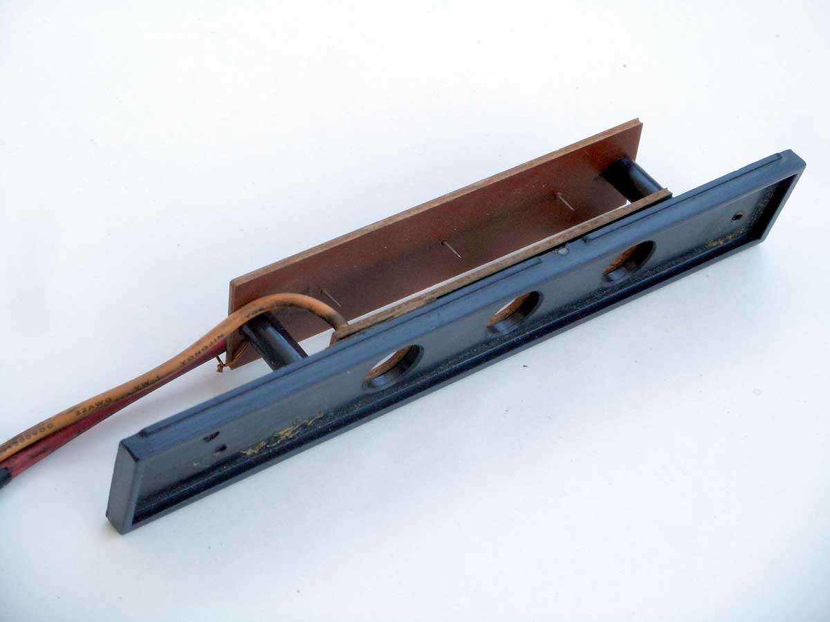
I wonder what's under the plastic hood? Let see : )

OK. We have direct connection to dipole and transformer based on short end coax cable. For interest, measure its length.
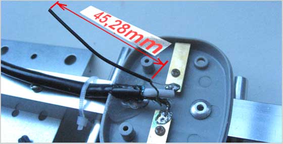
Of course, it does not speak a lot, since it is necessary to know the properties of this coax cable at the beginning. But the size and location of the dipole (brass) can be very useful in the future.
Reflector and directors made of the same material - aluminum pipe, 8mm diameter (outer) x 0,8mm.

They are installed unbalanced in square profile (16 x 16mm, outer).

Now, without unnecessary details, drawing of this antenna as follows (all in mm.).

*1. The distance between centers of last director and dipole (active element) - 25 mm.
*2. Distance between first and last element - 451 mm.
*3. The antennas length, from the beginning to the end - 565 mm.
At this moment.
I developed some antennas for a similar frequency range. Short look says that this antenna is far from perfect. And I'll be perfectly happy if she would give 6 dB gain at 2450 MHz. But I could be wrong.
Some reasons why I think so.
Firstly, any antenna will work. Even beer can or a small piece of wire. The question at what frequency and what gain can be obtained.
Second - diameters of elements too large for such short wave (for 125mm (2400MHz) max, diam. must be < 2.5mm). This gives great uncertainty in the usual calculations.
Third, that even a well-designed antenna needs to be tuned. It may take some time and the result may be very different from your calculations. Sometimes - very far away.
On the other hand, a long time ago another antenna was made by DLOSZ and tested (Karl Rothammel, Antennenbuch, Berlin. 1975). For a frequency of 435 MHz, its dimensions were the same as in the figure.
It's a bit away from calculated sizes, but it works (at least, no one in the last 52 years has shown the opposite :).
A similar antenna that supposedly works.
A similar antenna was found on backtrack-fr.net and looks like:

But even in this case, the sizes of elements and distances differ for my antenna.
Anything can happen or never say never.
Whatever assumptions about this antenna I would do, it's nothing until it tested & verified. By this, I'll do next.
The theoretical pattern of H/V field can be such:
On the other hand, 15dBi antenna HAI15SC, from Hawking Tech.,
works better and has a better gain factor. The latter was checked after an RX-level comparison with help of simple Wi-Fi card.
More information about WiFi antennas for 2,4GHz, and how they are made, you can be find here.