Antennas Frequency Bands.
WiFi: 2.45 GHz
Bluetooth: 2.4—2.48 MHz
WiMAX: 2.5 GHz—3.5 GHz, 5.8 GHz
UWB: 3.1 GHz—10.6 GHz
GSM: 380—1900 MHz
CDMA: 1850—1995 MHz
GPS: 1176.45 MHz; 1379.913 MHz; 1381.05 Mhz; 1227.6 Mhz; 1575.42 MHz;
3 dBi antennas.
A. The simplest, with ~ 3 dB gain.
It was used in simple routers/bridges Cisco and Linksys.
All brass cylinders are same as from 'chicken farm', od = 4,4 mm x 0,3 mm. The length of the central conductor of the coaxial cable, that sticks out of brass cylinder, may vary from 25 to 29 mm.
Either way, the final drawing is the antennas that work well. All dimensions in millimeters.
Theoretically, the ratio of the outer diameter of the coaxial cable to the inner diameter of the brass cylinder is important. But not so much.
B. The simple and similar, with little more then 3 dB.
Another type of very similar antenna.
2 metal cylinders, 5,2 mm diam. at 6 mm distance. Two solder points on the next photo.
The main dimensions on the drawing below.
This antenna works better than first one.
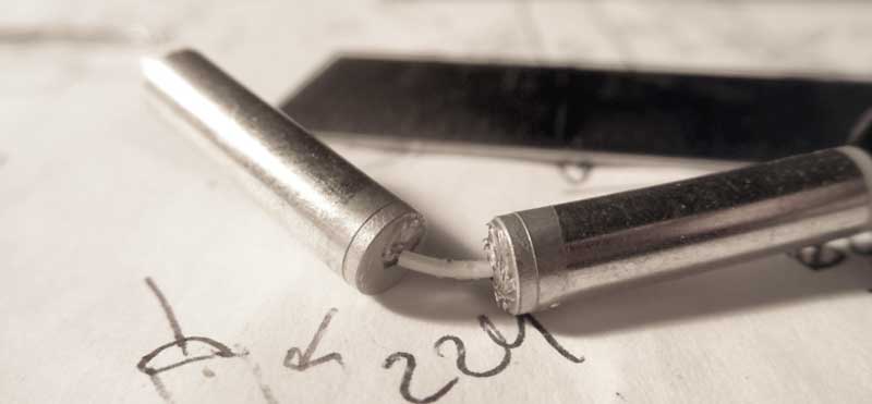
C. Dipole, from 15 elements Yagi antenna.
Half-wave dipole made of two brass plates, 0,4 mm thick.

Coaxial Cable "Balun" Transformer (45.3 mm long, shorted in other side) balance asymmetric cable.
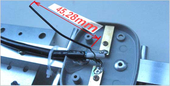
A simplified picture shows the dimensions of the elements.
Such a dipole has a resistance of ~73 ohms (not a 50 Ohm, which is necessary). But despite of this, the overall gain of such '15 element' Yagi is only slightly less (~13 dBi) than gain of Hawking '15dBi Directional Corner Antenna' (compare model: HAI15SC).
The theoretical pattern of H/V field can be such:
More info about this YAGI is here.
5 dBi antennas.
It can be assumed that this is a 5/8 omni-directional type of antennas. Whichever name is, they all are very similar.
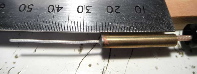
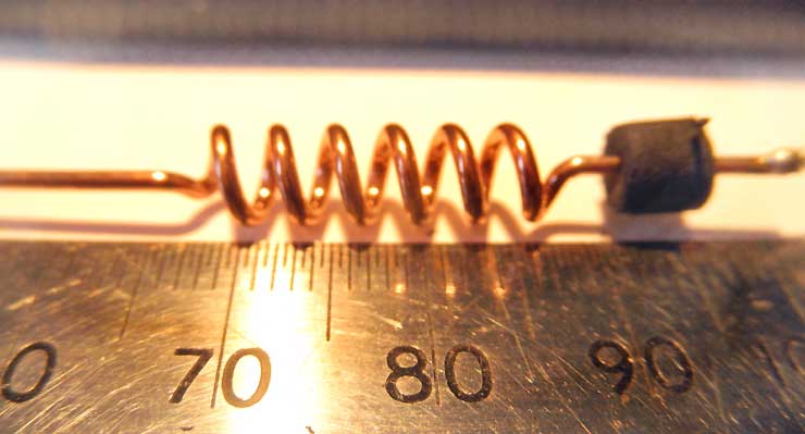
D. 5 dBi, EVDO's WiFi bridge.
The basis of this antenna is 1 mm solid copper wire. The metal cylinder around the coaxial cable is the same.
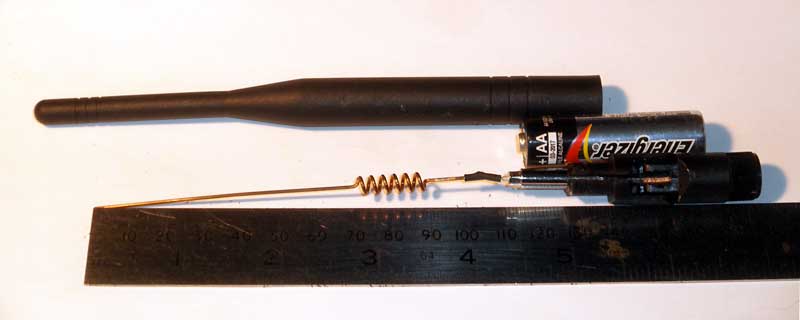
The coil is a significant part of antenna. Do not try to make it sloppy. For this diameter of the copper road (1mm), it should be exactly as in the photo.
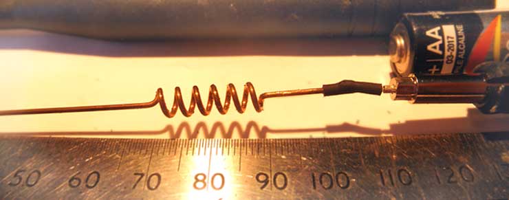
Dimensions that are critical, in order for the antenna to work with 5 dBi gain. Try to do it as accurately as you can.
In the drawing, only a critical dimensions. In order to make a good antenna, these dimensions should exactly match the pattern.
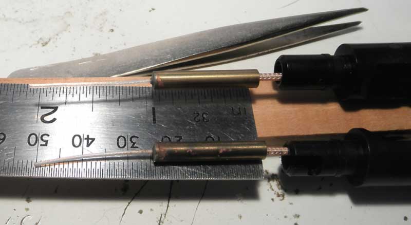
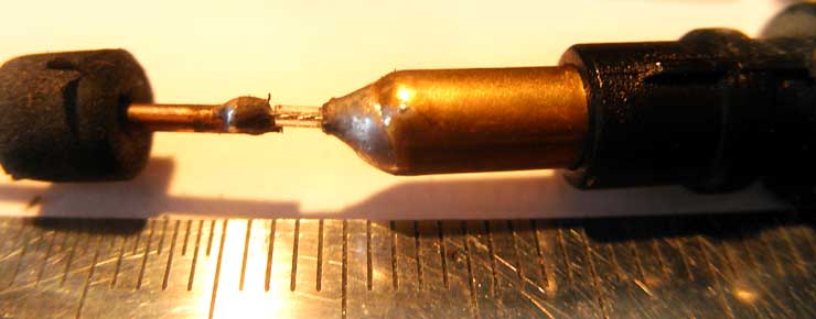
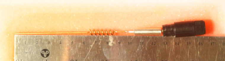
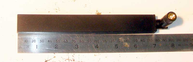
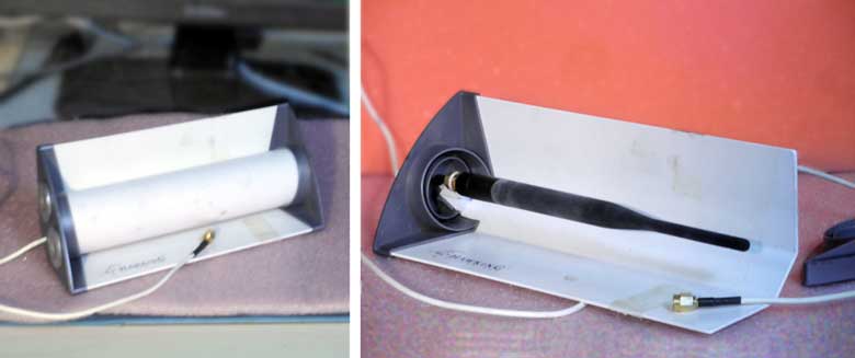
E. 5 dBi ALFA, came with AWUS036NH .
This antenna came with ALFA 1W USB WiFi card. Despite the fact that it is too thin, it works very well (I mean the antenna gain = 5+ dBi).
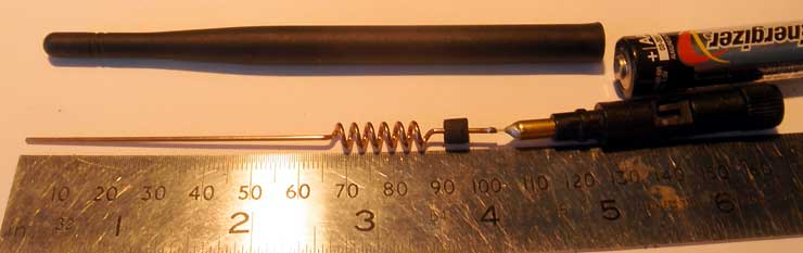
It is made of a 1,2 mm copper. Therefore, the dimensions of the coil are different. The black cylinder, on the right, is a rubber's foam bushing.
The left end of antenna aligned with 0 mm of ruler. Therefore, the sizes are real ( mm scale ).
And it has two solder points.
And again. If you make a similar antenna, then be sure that the dimensions are exactly the same.
In any case, it works better than I expected.
F. 5 dBi, Hawking.
This antenna is inside another high gain antenna. Unusual is the material of the rod. This is a brass or very strong copper.
The coil has a slightly different design, where all sharp corners are rounded. It is very pleasant that the cylinder is covered with silver.
Has standard male SMA connector: male body (inside threads) with male inner pin. As part of Hawking HAI15SC, this works very well.
G. Unknown Antenna.
Dimensions, a long time ago, was taken from the Internet. Only for comparison.
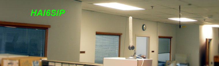
H. Roof mounted antenna..
Without sizes. This is an antenna that is mounted on the roof of the car. According to the datasheet, this should give us more than 5 dBi. The design is simplified and maybe it works.
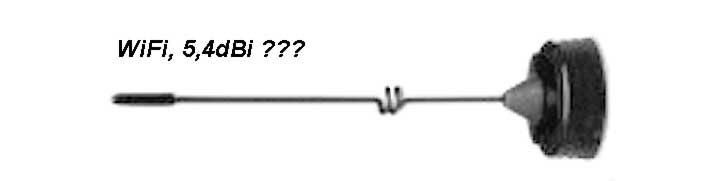
Because such antennas are mounted directly on a metal roof, a mirror effect arises. This leads to the fact that the antenna becomes twice as long as its geometric dimensions.
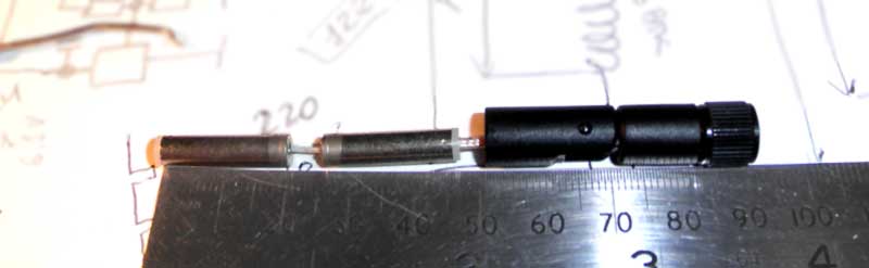
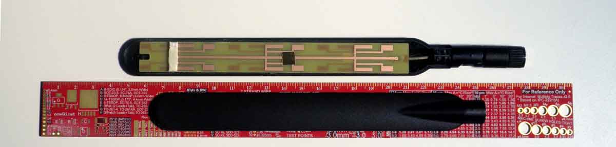
I. More then 5 dBi and less then 9 (pn: SAA05-220610-C).
This antenna is interesting because it's hard to understand how it works. The manufacturer or parts number was not found. Indoor. Comes with a magnetic base and cable.
Under the flat hood there is something between multi dipoles and antenna array.
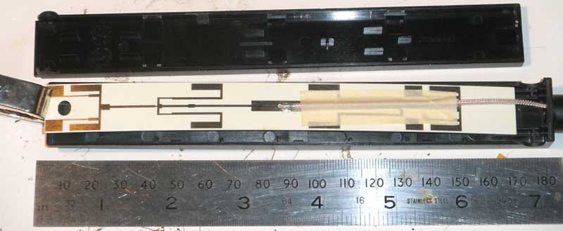
Manufactured as a printed circuit board on RF material, with silver surface finish.
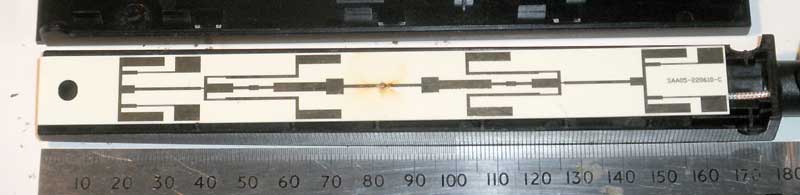
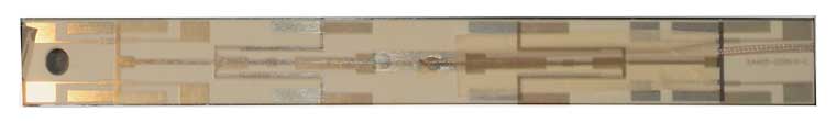
The best thing we can do is to combine the top and bottom layers in a photo editor. Perhaps this will help someone to figure out how this works.
Finally, when I dismantled it, it became clear that this is a directional antenna. This screw up my test result, which showed an average gain in the horizontal plane at level ~6 dBi. I'll redo it later, but for right now - we have what we have.
In our equipment, we use antennas that cover both Wi-Fi ranges.
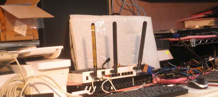
HAI6SIP has been working for many years. Whatever happens, it continues to work.
The antenna has two layers, with complex topology. Both of them are combined together for clarity.
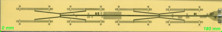
Radiation patterns are found on the manufacturer's website.
K. ASUS, 9 dBi omni antenna.
Regardless of my attitude towards to this manufacture, this antenna works exactly as 9 dBi.
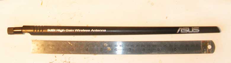
Inside, a single side PCB, 0,75 mm thick, covered by black paint. Just one label, as you can see on the top corner.
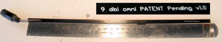
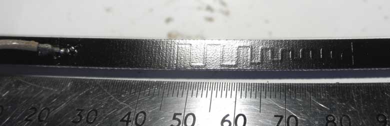
Printed coils / delay lines, which are visible in the photo, connect the three elements (53,5 mm x 5 mm) together. Only the first inductance has a built-in rectangular block (4,6 mm x 2,5 mm) that is visible near 47 - 49 mm on the ruler.
I could clean this antenna of paint and put it in the scanner to get an exact copy. But I'm too lazy to do it. Approximate drawing, below. Again, all sizes in millimeters.
I use it as a base antenna for measurements and don't break it yet. In general, it's nice to have something good and reliable in a small lab.
L. Hawking Tech., 15 dBi.
For this, high gain antenna, the manufacturer found a simple and effective solution to convert a regular '5 dBi' antenna to directional '15 dBi', using aluminum 'corner reflector'. And it works well.
The drawing shows main dimensions.
And radiation patterns:
M. 0,5dBi SMD antenna, Johanson Tech.
Antennas with a small gain, exist, too. Small in size and have their application.
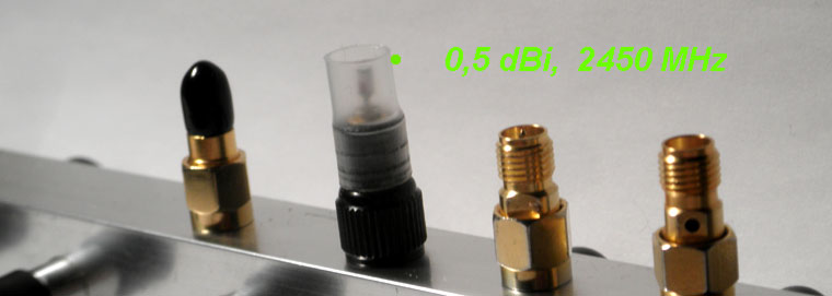
At the core, a spot-mounted antenna for surface mounting. Interestingly, the only marked side is connected to the antenna. Other side is not connected to anything.
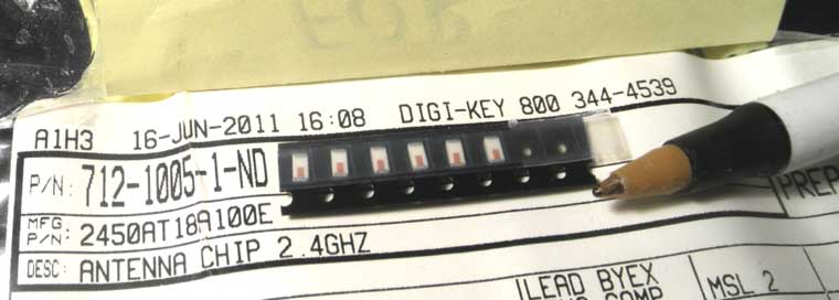
Small size and weight allows soldering this on the center wire of coax cable. No matter how it looks, this antenna works, already, 5 years.
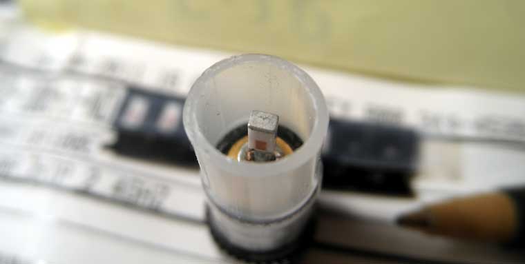
It is probably useless at home, but it helps a lot when you need to get a point source of RF radiation.
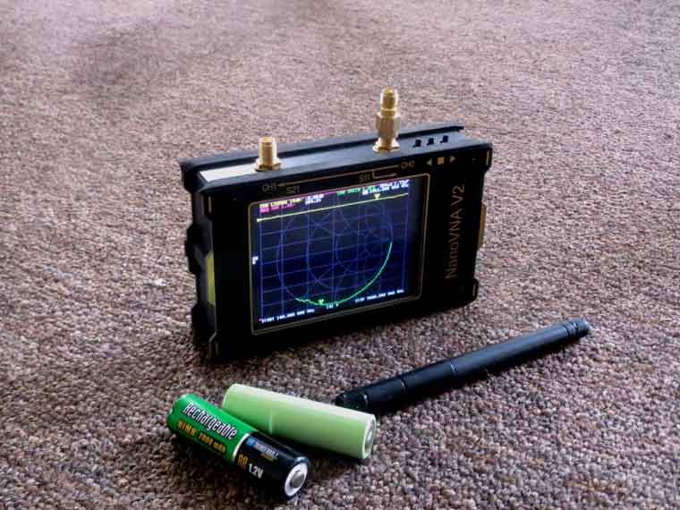
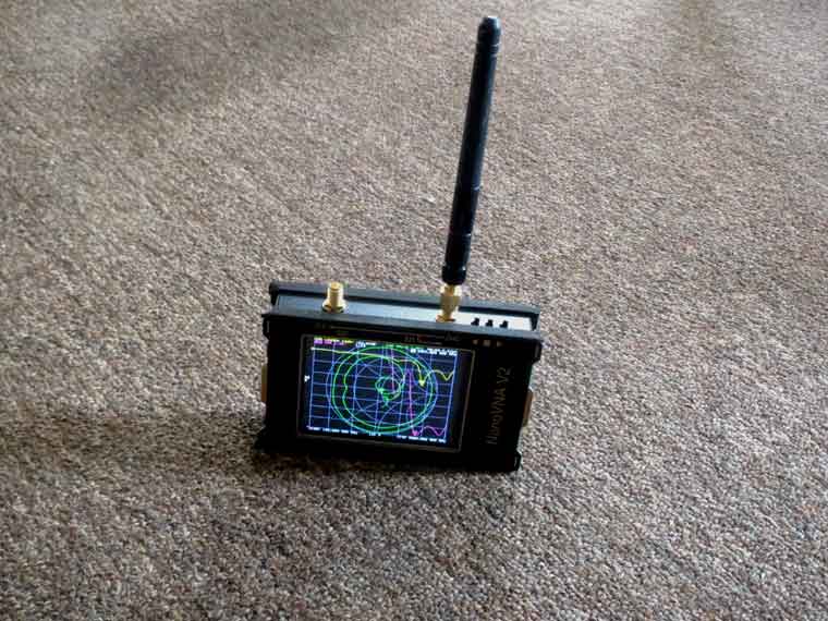
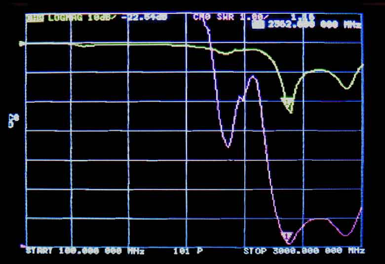
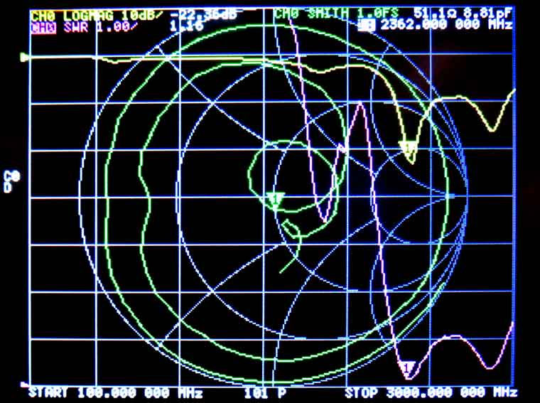
This is much easier than it sounds. Any Vector Network Analyzer (VNA) will do it for you. You just need the frequency to be in the range.
This one is more than a fit. On the screen, the voltage across antenna is shown in yellow, the SWR is lilac (purple), and 'smith chart' is green.