'CRTV-time' at WIN Enterprises Inc.
What is it about.
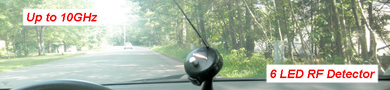
You will see a detector circuit that catches a radio signal in the range of 100MHz-10GHz. The upper frequency is determined only by diodes that you can pick up.
Hi-Story.
Actually, I needed a simple, reliable and foolproof RF detector, which I could gather from general use components . Search the Internet, as usual, did not give anything useful. Therefore, we have what we have from parts that I have.
Schematic diagram.
The radio signal is received by the antenna, and rectified by D2,D3 with a voltage doubling. Further, the DC voltage is amplified by the transistor Q1 (approximately 10 times) and is sent to the LED indicators. Transistors work as current amplifiers and threshold elements.
The Power Switch is not present because in the standby mode (when R3 is in the up position) the circuit consumes about 0.3 mA. With this current, the AA battery pack will be discharged in one year. The top current ~ 10mA.
How it works.
Schematic diagram, which looks complicated at first look, is actually very simple. It can be divided into several parts that work together (and they will work separately as well ). RF detector, DC amplifier, voltage shifter and LEDs drivers - that's all we have. For simplicity, they are separated by dotted lines.
A simple detector (D2,D3), with voltage doubling, rectifies RF signal and converts it into a DC voltage. The transistor Q1 will start to open when this voltage increases to ~1,2 Volts (from "+" to "gate" of Q1). The voltage drop across resistors R6, R7, R8 will start to increase, and when it reaches 0.8 volts, the first transistor Q4 will open, leading to the LED D6 ("Low") will light up. If the voltage increases further, then the same will happen with Q3, Q2 and D5, D4.
Theoretically, to make the circuit run, the input RF voltage should be 1.5 volts or more. Of these, diodes require 0.3 volts, each, and MOSFET transistor - around 1,2V to be open. The voltage shifter (var. R3) with "fake ground" (C1, C3, C4) allows it to be compensated. At same time, R3 allows to vary RF sensitivity of the circuit.
* LED D1 is used as zener, and captures ~ 3V drop, at 0,3mA.
** In the real circuit, the number of LEDs is increased to 6. Section "R6, R9, Q4, D6, and R14" is repeated 3 more times.
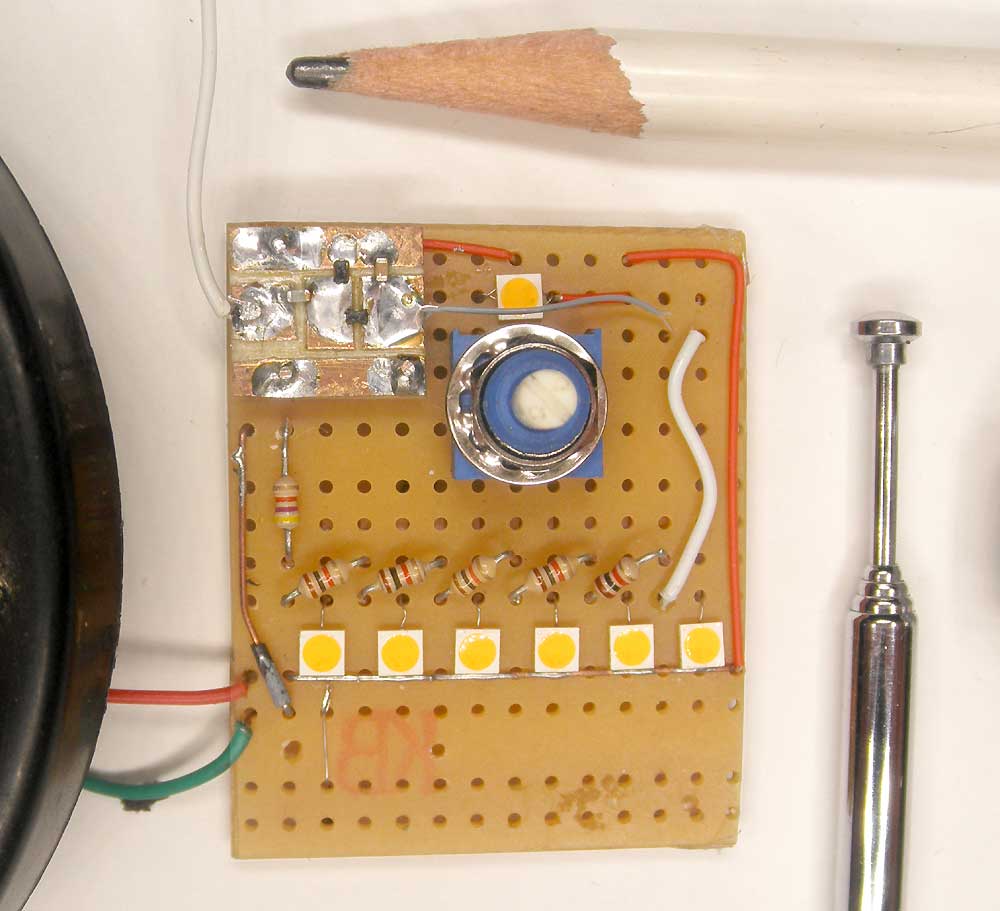
Mount everything together.
A trip to a 'dollar store' is usually very useful. Any holders for 3 AA batteries are suitable. In my case it was funny looking LED light . The only thing I added is a flat lens, through which light is transmitted from the LEDs.
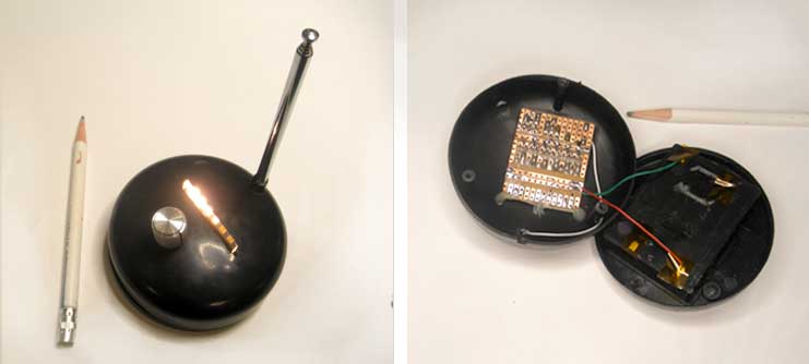
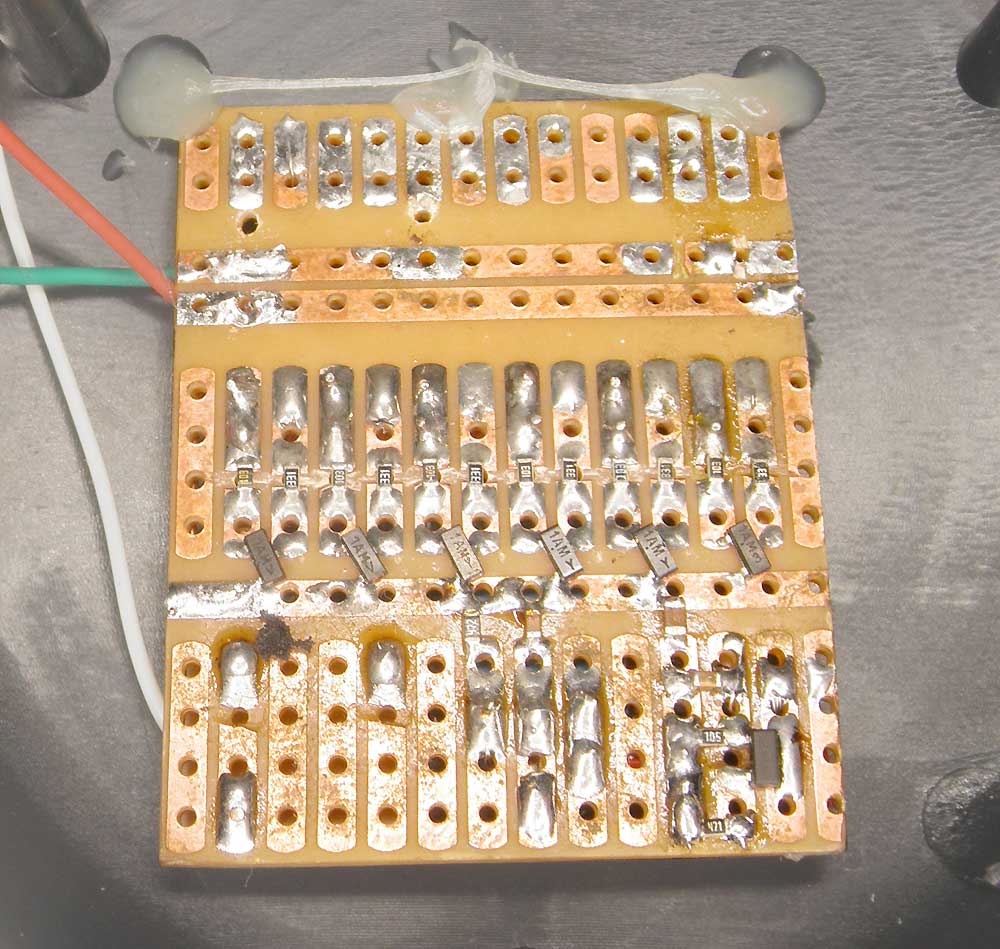
A piece of universal board and SMD components allow you to do this quickly, enough. In the beginning, we set the LEDs on the position where we like, and everything else around. The upper resistors connect and transmit signal between points. A few more jumpers and everything is ready to go.
.
 .
.
Only one part is separate. This is the RF detector, itself (upper left corner, left photo). The reason is that it is much easier to do on a separate piece of good quality board and not be dependent on the quality of the main board material.
Sources of SMD components.
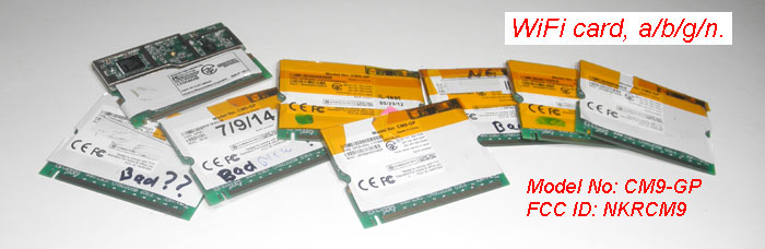
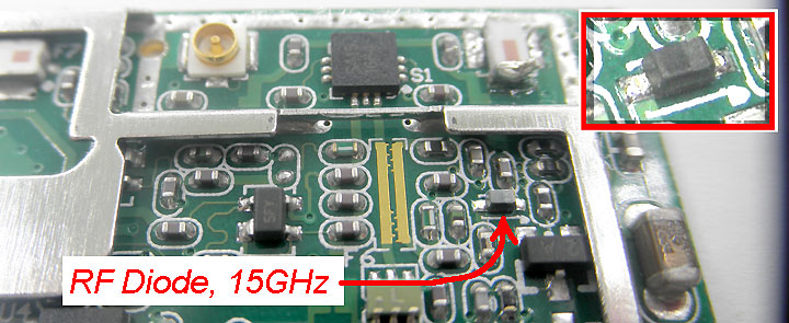
The first thing you should have is RF diodes. At the end of this page there are reference data for similar diodes, where you can get the idea of what you are looking for. You can start experimenting with any diodes, but we'll skip this.The best free source - the old WiFi cards (/b/g/n are good, /a is the best), where these diodes work for SWR / Power measurement. Next cards are a good example.
Diodes have a small size (1,2 x 0,8 mm) and located close to the footprint, which is hard to confuse with anything else.
Here, on FCC website, a schematic diagram of such WiFi card: FCC ID: Q7UNOW-WL.
Transistors 2N3904 and NDS352 (as well 2N7002) are usually widely present on motherboards. They do not have full labels. The next picture gives an idea of how they are marked and what it really is. On my board they look like.
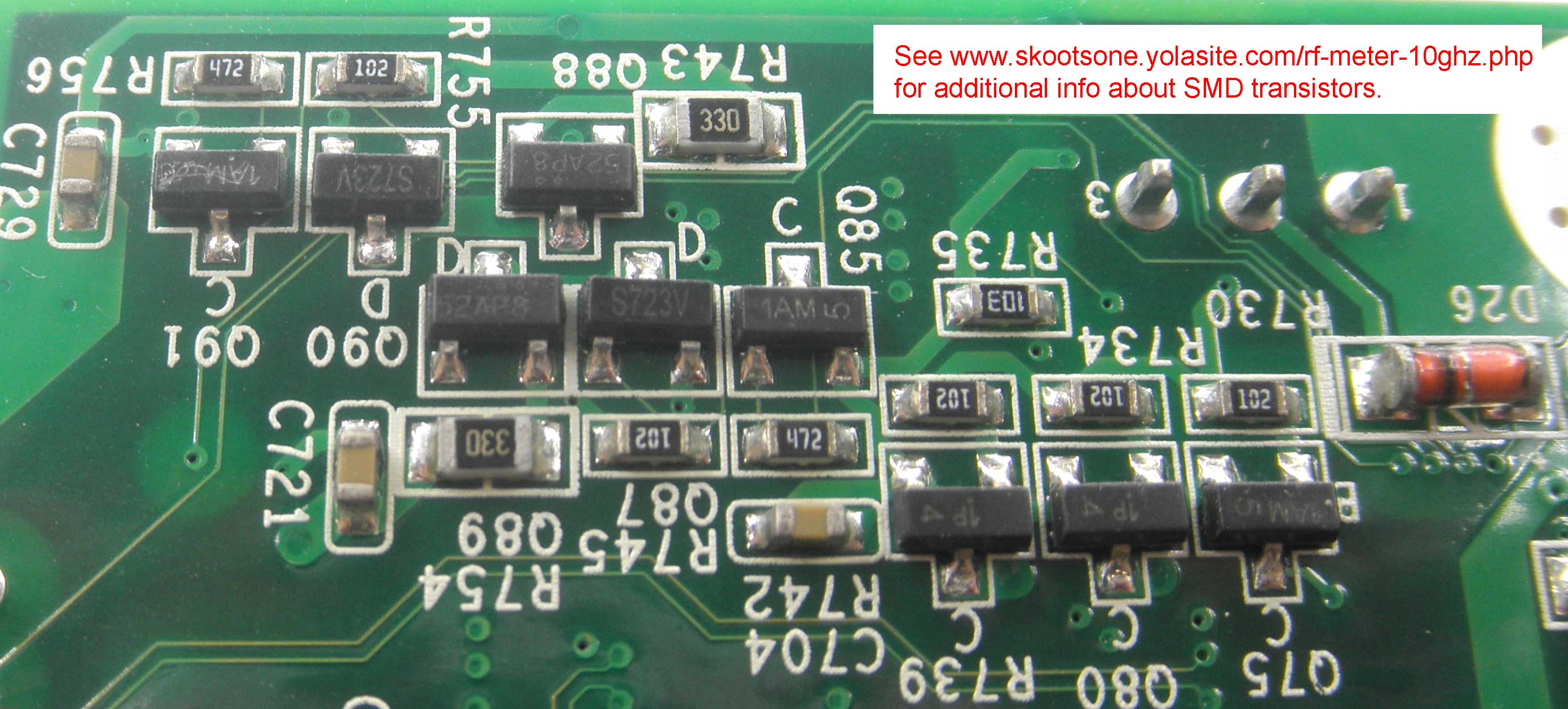
It's good to have a circuit diagram (never happens). For a photo that is higher I have it by accident.
LEDs ... The 'dollar store' is a good source of white LEDs, too. Any lamp contains them. Depending on your luck, you will get from 12 to 48 white LEDs from each. Of course, it's not easy to get them out and a few will become broken during this process. But it's worth it.
Source of an enclosure.
The same store is a good source of project's enclosures, if you add a bit of fantasy. This is an example. Under the hood there is 6 LEDs plus drivers board, in the trunk - a detector, R3 - behind spare tire, and the battery location you see.
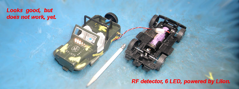
* This "car's" project does not run yet, but will be completed soon. Link under the picture.
Works better than you think.
If you repeated everything exactly, then you will have the following.
- The detector will find the RF transmission of your home router (Linksys WRT160N) from a distance of 0.5 meters.
- Transmission from FRS radio (Maxon TK-14VWX, 100mW) - from a distance of 3-5 meters (all 6 LEDs ON).
- Radio emission from a microwave oven, in your kitchen, the same will be reflected on the LEDs. Depending on the quality of the front door insulation and total power, it will light all LEDs, from distance 1 - 5 meters (3 to 15') .
* Just remember that the length of the telescopic antenna should be matched. It should not be long or short. It must match the frequency of RF signal that you are taking (or are about to take).
** The length of the antenna should be a multiple of the wavelength. In this case, it should be noted that the piece of wire that the antenna is connected to the board (in my case, white wire, 10cm or 4" long) is also part of the length of the antenna.
*** Do not switch ON the empty microwave oven. Just do not do it. A glass of water in the middle will protect you from problems.
It's all...
Enjoy the search for radio emissions, which you previously did not even suspect. Believe me. You will learn a lot of interesting and unusual things.
Good luck :)
All schematics are for reference, only.
------------------------------------------------------------------------------------------------------------------------------------------