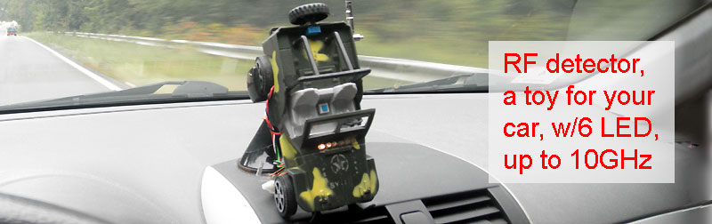
A simple toy that travels with me in my car.
What is it about.
Schematic diagram.
The 'Power Switch' is present in real life. It simply breaks the power from "+" battery and makes it possible to charge Li-Ion.
In standby mode (all LEDs 'OFF') the circuit consumes about 0.3 mA. The top consumption (all LEDs "ON') ~ 10mA.
Mount everything together.
The "Dollar Store" is a good source of project's enclosures, if you add a
bit of fantasy. This is an example. Under the hood there is 6 LEDs plus
drivers board, in the trunk - a detector, R3 - behind spare tire, and
the battery location you see.
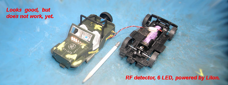
The main difference from the previous project is that schematic divided into three boards.

The main reason to do this was to move RF-detector far from LEDs. Otherwise, the current pulses from the LEDs are received by the antenna as a "useful signal". As a positive feedback it trigger all LEDs 'ON', unpredictably.
*** Added: This "car's" project runs, non-stop, for month (as you can see on the top picture). No problem, yet.
Works better than you think.
For what ?
As the second, it is a project "How to power microcontrollers from ambient RF radiation". The latter was focused on the development of antennas capable of doing this. Some pages you can see here, just in case. Different antennas are used, but they all convert the RF energy directly into DC. As a result, I can connect all antennas by DC and get rid of all complexities existing in RF design. it also works well and does not require knowledge of "RF Engineering" from MIT or other universities!
It's all...
Enjoy the search for radio emissions ... & learn a lot of interesting and unusual things.
Good luck :)
/* In case of questions, you will find my e-mail, below.*/
All schematics are for reference, only.
------------------------------------------------------------------------------------------------------------------------------------------