
Simplicity at the first. Just like RF design, some times.
3.2.2 Convert AM/FM Radio to Air Band (110-138MHz).
Simple aim, Sony ICF-C240, on the photo above. Target - to convert it to Air Band and listen air dispatchers & pilots talks.
This can be done in different ways, but we choose the classic one. Preset (re-tune) FM receiver from frequencies 88-108MHz to 110-140MHz or close to that.
It's simple, but strategically we have one problem. The receiver is configured to catch FM broadcasting with wide frequency modulation, and here we can not change anything (in a simple way). At the same time, Air Band works with amplitude modulation (AM) which is incompatible with FM detector. Here the trick - any AM contains small portion of FM, which badly (with a very low output level), but can be detected. And it does not work in the opposite way (FM does not contain AM). Therefore, we move on.
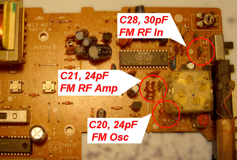
As I said, reworking is very simple. We will rearrange the three oscillating circuits up in frequency by decreasing the capacitance (by adding additional capacitors in series with those already on the board). But for this, you first need to make sure that the radio works well on the FM band. This simple step is usually skipped, but in vain. After that, you can disassemble the radio. We will be interested only in the radio chip. In my case, it was an CXA1019S, as you can see.

CXA1019B is probably the best chip that is suitable for rework. Plus, Sony made the schematic very easy to understand, I don’t want to say that it is to copy and paste from datasheet, but very close to that.
You can search for a specific schematic diagram, but the CXA1019 datasheet (or copy here) has everything we need. Here is what interests us.
It remains to find it on the board, and see the actual values of the capacitors involved in it. This is what I have (the values of capacitors on your board may, and most likely, will differ, but it does not matter).
The simple way is to not think about anything and reduce the capacitance of these capacitors by half. It works well. But if you need to do exactly, then all this can be recalculated.
It looks complicated, but in fact, everything is much simpler than it seems. Two formulas that make our day ( L=k*sqrt(n) & 2*pi*f= 1/sqrt(L*C) ). If you put everything in Henry (L), Farad (C) and Hertz (f), then everything works.
 The first formula is if you want to change the values of capacitors, second - if you ready to rewind new coils.
 You must do:
a) recalculate the input circuit (C28 in this case) from the average frequency of the FM Band (108-88=~100MHz), to the average frequency of Air Band (140-110=~125MHz);
b) top frequency for FM oscillator (C20) from 108+10.7=118.7MHz to 138+10.7=148.7MHz;
c) top frequency for FM Amp. (C21) from 108MHz to 138MHz;
d) сalculate the effective capacitance of two cap. in series.
Skipping the magic of calculations, which does not interest anyone, I got the following. Remember that the top of a variable capacitor has a trim capacitors (~10pF) that you can use for fine tuning (or if you made a mistake from the first time).


That's what I really have after this modification. Must say, that it is very close to my first calculations.

As a tradition, good news at the beginning. It really works and I can listen Air Band (110MHz to 138MHz, AM) through this modified radio. And the good news ends there.
Problems, problems, problems.
I do not want to be annoying, but the reality is not as good as it should be. Reading on will be a waste of your time, so stop here if you have no other reason.
1. Inaccurate calculation of the capacitance of С28 (band-pass filter along with a coil printed on the other side of the board). As a result, I can hear the signal at 152MHz (digital data broadcast) in the last quarter of the scale. Increasing the additional cap (C28 +) from 27 to 43 reduces this, but does not eliminate it completely.
2. Modulation. The wide frequency modulation used in FM has a frequency of swing ~ 50 kHz. AM that we are trying to receive - only 5kHz. The difference is 10 times, and the same at the audio output. As a result, you need to set the volume control to the max and enjoy receiving the signal in a noisy environment.
3. Tuning. We do not have broadcasts in Air Band. Voice messages are very short (5 sec. or less) and are very rare. In this case, it is very difficult (impossible) to tune to a specific frequency. Many tricks to do this, but in practice - it is a nightmare.
4. Sensitivity. Most of these AM/FM radios are not designed to be highly sensitive. They work well with a strong signals and are absolutely useless for the weak. The air Band is closer to the last. For example only, the signal levels at my place (5 miles from the airport).


You can enlarge the pictures, but the conclusion will be as follows. To achieve the same signal level (signal-noise), you should be at airport, at least, or use a specially designed antenna (what I am doing to make & it work, some how). But let's be realistic.
5. And the last thing that no one likes to hear. A simple super regenerative radio (such as this (not ready) or similar), on one transistor (plus 2 transistors audio amplifier), works better and without any headache. & beats in all respects such a re-tuned FM radio.
Is this the end of the story?
Nop. It is possible and it works well. But it requires a little more than replacing 3 capacitors or pushing the coils apart on the board. Just a little more needs to be done. As an idea, this is a simple external converter (just picture on the top) that is easy to repeat and works independently. Tune AM radio to converter's frequency and enjoy. And, of course, this is not the last solution to the problem. Just the rest are a little more complicated and can not be done in a few hours.
It is it. Any questions by e-mail (see end of the page).