Was done enjoying Friday afternoon
"hackathon" at WIN Enterprises Inc.
An idea was, to make low power step-up DC-DC converter, to power MSP430 micro-controller from one AA battery. And of course, from parts that are widely available.
The second requirement is the minimum power consumption at IDLE, in order to run AA battery as long as possible.
Nothing is easier than re-using the solar powered outdoor light I did not come up with. And that's what I have right now. On the schematic DC-DC converter from 1.2V to 3.3V, 15mA (max). Current consumption without load - 20uA.
U1 (ANA618,YX8018 or YX801) works in the same way as described in datasheet. When the output voltage reaches a certain level (~3,3V), the transistor VT1 opens and turns off the converter. If the output voltage drops, the converter will turn on again, and cycle will repeat.
The circuit acting as high efficiency fly-back converter with PWM.
Next graph gives an idea of how the output voltage, output power and total efficiency are related to output current.
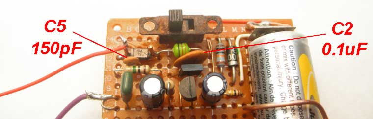
If you doing to repeat this circuit, then all necessary comments exist on schematic diagram. But two things must be done. Capacitor C2 (0.1u) must be connected directly to U1 (+V & GND). And you should not forget about C5, which can be 100-1000pF. In general, you can do whatever you want, but it will cost you a loss in efficiency.
------------------------------------------------------------------------------------------------------------------------------------------
17.28.2. How it works.
Most of these converters work the same way and do not care about the presence of solar panel. Therefore, it can be replaced by an ordinary switch or nothing at all. This will work as boost converter with a fixed switching frequency. At about 200 kHz it will dump power to LED.
This works because at night time solar panel does not produce electricity and works like a simple 1k resistor.
Some chips have protection against over-discharge of
Ni-Cd or Ni-MH battery. This turns off the IC when the battery voltage
drops below 0,9 Volts (as QX5252F). But I would not have counted on it.
In any case, if you have solar light, then you have a
ready-made voltage converter. Small additions and we have a simple PS
with limited voltage and current. Here the inductance L1 limits output current, and LEDs (works as zeners) limits output voltages.
According to the table, you can make a simple meter to check coil's inductance (described here). But let's go back.
The idea of draining all the power, regardless of the current consumed by the load, looks stupid. But it depends on how to approach to it. For example, charging for lithium-ion batteries will work fine. The LEDs (white and green) will indicate the end of the charge state (if this occurs).
It will take forever to charge your smart phone, but for battery from a small RF helicopter (3,8V 200mAh) it will take a reasonable amount of time.
If we go back to the first schematic diagram, the final version will look like.
Not a rocket science, everything works according to common sense. Capacitor C5 allows to turn U1 ON and OFF very quickly. You can see this on wave-forms taken at IDLE, from points A & B, shown in the last schematic diagram.
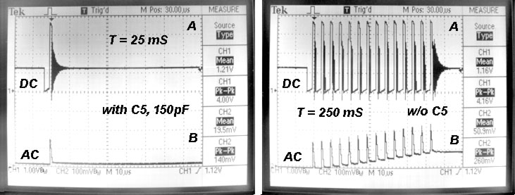
An explanation of what happens on the oscillograms is long and boring. Therefore, as a short result - С5 reduces output ripple voltage from 260mV to 140mV, and improves the overall efficiency of the circuit.
Power consumption. From 20 uA that the circuit consumes from 1.2V battery, 9uA goes to the voltage divider R1,R2. Increasing total resistance to more then 2M is not possible, because the circuit becomes very sensitive to humidity and temperature (the output voltage begins to drift).
Let's stop on this. Any questions by e-mail.
* 3. Solar Garden Lights based on Integrated Circuits, schematics (here or link under top banner)
* All schematics for reference, only.