Simply, I like to restore old things.
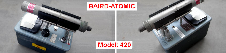
Biard-Atomic, model 420. Back to life.
I bought this device in "excellent condition", as you can see in the picture. Except that it was just interesting to see what in the middle of the device from 1967, I had more reasons to do it. This is a Geiger–Müller tube that probably good, the DC-DC converter, which I'm too lazy to do myself and I want to have another radiation meter, just in case.
The fact that it turned out to be completely dead did not surprise me at all. But thanks to the old tradition, when each electronic device was accompanied by a schematic diagram and detailed instructions on how to work with it. You can download manual in pdf format from here (same copy), or other copy from here.
From now on, you have everything you need to restore this radiation meter. Then you can see what I did.
Short inspection.
After opening the lid, it turned out that it was still worse than I had expected. The main reason - D-batteries, which for last 15 years led to the corrosion.
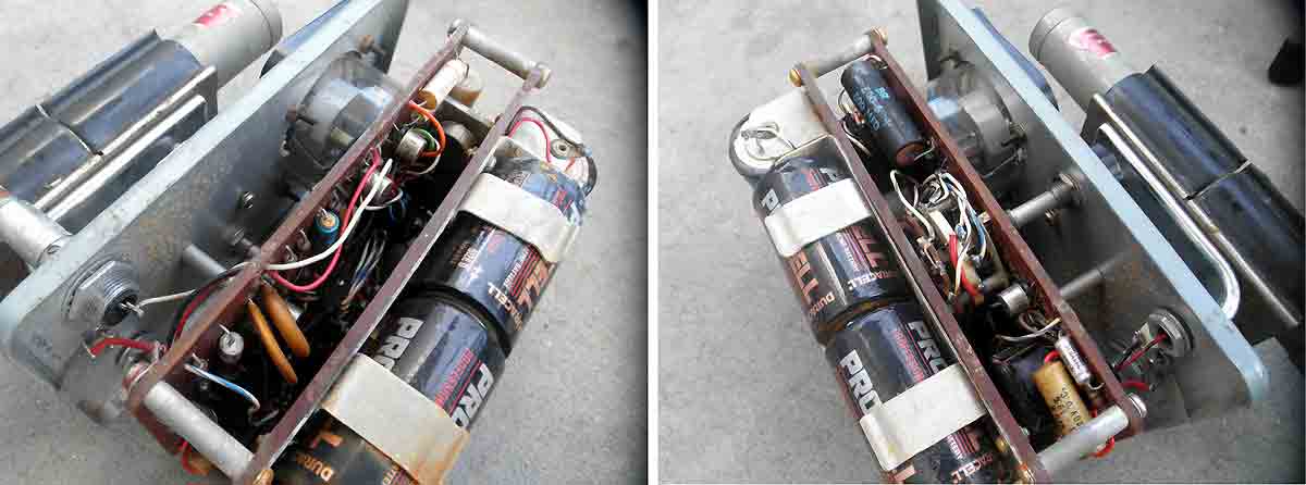
In addition to the board, the 50uA head failed to return to zero. Not a big deal. The lower spring turned out to be rusty and it took about an hour to clean and restore its properties.
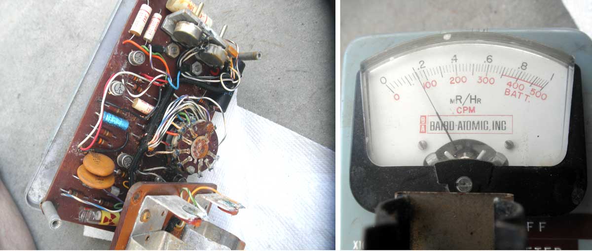
Brush-cleaning with water, ammonia and alcohol, gave everything a proper look. Leaving everything to dry, it's time to see which Geiger–Müller tube is in the middle.
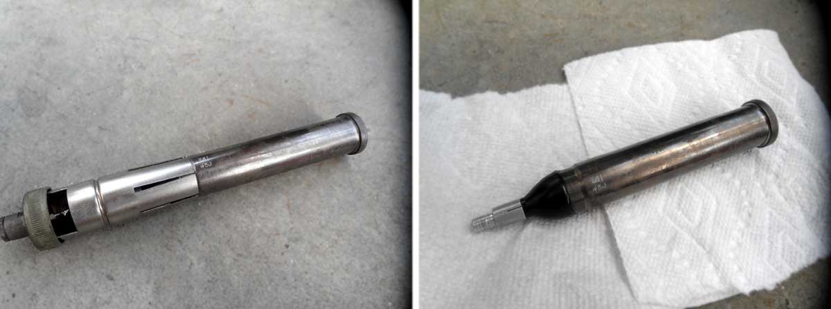
Side labeling is meaningless. Similar tubes that are in production to this day - 722, 7225 or 7227. I'm not sure that someone is willing to pay 190$ for each, but it's possible to buy.
In any case, the positive aspect of these tubes is that they are sensitive to alpha radiation. To do this, there is a window at the end of the tube through which the alpha can pass into the middle. In normal condition it is covered with a cup which has a small hole.
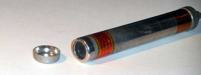
Just remember that if you opened this lid, then readings from the scale should be multiplied by 10.
The first run.
After installing 5-d batteries, nothing happened. Apart from the fact that one transistor overheated immediately. It turned out that the transformer has a short which makes it impossible to run the DC-DC converter which feeds Geiger–Müller tube.
This is a time to see a schematic diagram that is not very complicated.
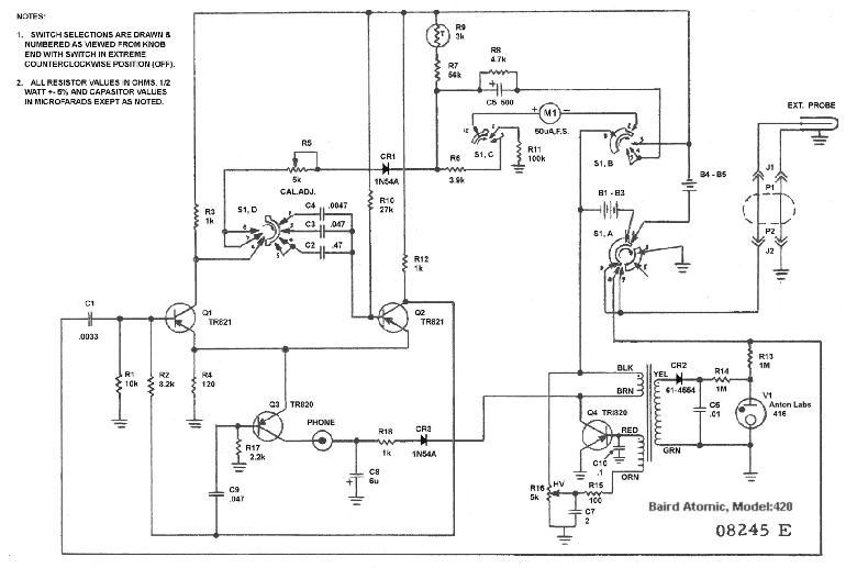
OK. A transistor and a HV-transformer need to be replaced. I'm not a big fan of buying original parts, even if it's possible. Moreover, in this case, I only need to check whether the tube works. On the other hand, we have tons of LCD monitors, where there are similar transformers working for LCD's back light.
If you do the same, then choose transformers that have 5 sections in the high-voltage winding. Usually, each winding section can supply up to 200 volts. This allows them to be used directly, without an additional voltage multiplier.
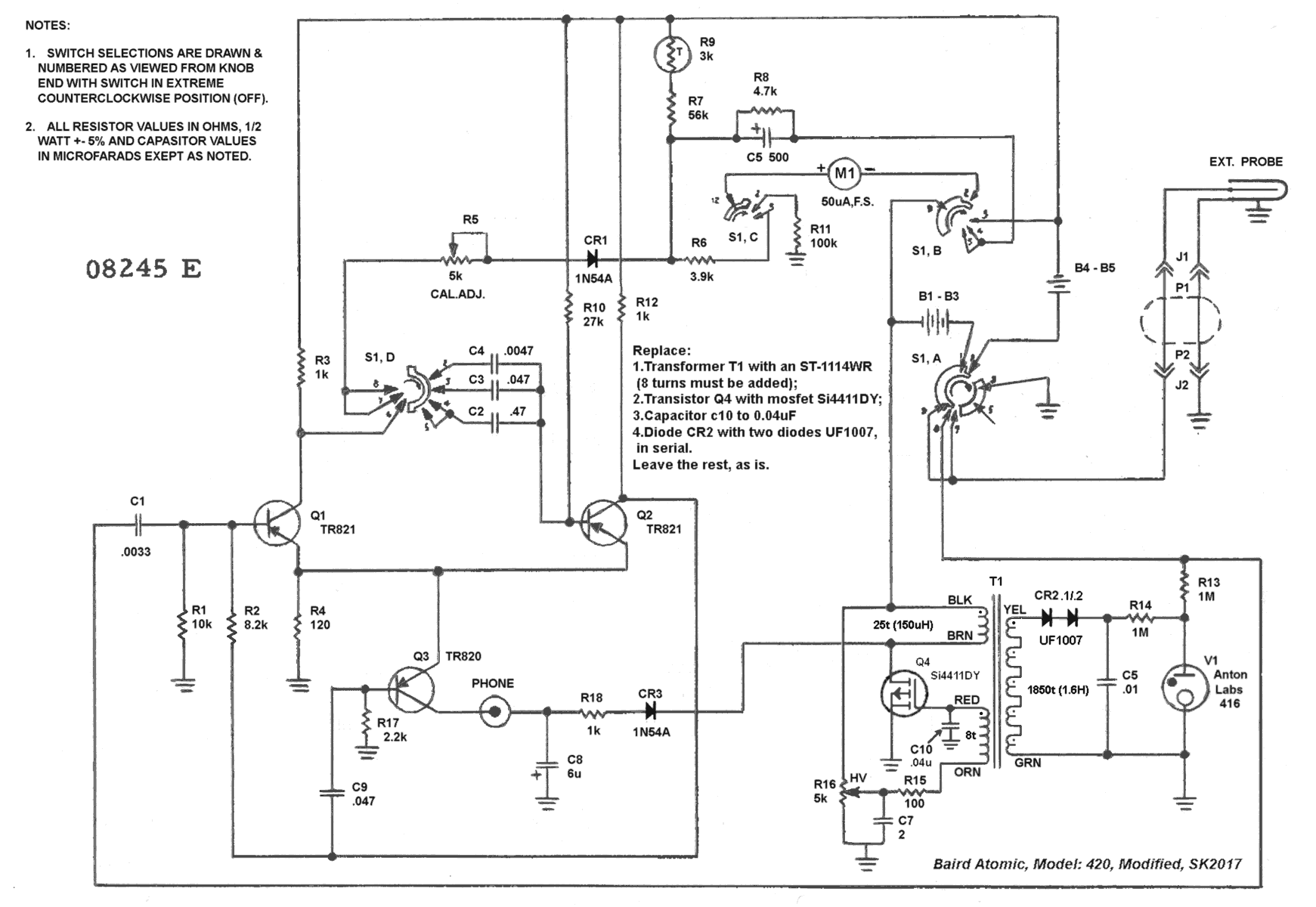
It is only necessary to add the winding over the primary. Usually this is one third of the number of turns of the existing winding. In my case for 25 turns - need to be add - 8. By the way, the transistor (4411, for real - Si4411 (P-Channel MOSFET)), can be taken from the same board.
A little more corrections to the schematic (for MOSFET) and we are ready to first run.
Before switching power on, for the first time, turn the variable resistor R16 (HV) down. Voltage on the middle pin must be zero. When the power applied turn it up slowly (raise the voltage) until the converter starts. Do not overdo it, it will kill the transistor.
After two transistors burned, I was lucky enough to get stable +900V at the output. And the second good news - the Geiger–Müller tube worked as expected. It had a slightly smaller count than new one, but this can be adjusted by R5 (CAL.ADJ.).
What should be done in the beginning.
When you bring such things to your home, it would be good to check if there was any residual radiation left in them. You never know where it was before you.
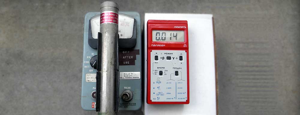
You must make two measurements with maximum duration (200 sec, at least), with the device side by side and without it. If the control device does not show any changes, then this is your lucky day. A third of these devices have residual radiation.
The final schematic and mod.
Everything works, and can be used. A few changes that make this device what I need - on the next page.
*** It was interesting to find a book dated 1946, and read about the radiation hazard.
Several chapters from it you can read too.
Several chapters from it you can read too.
1.MEASUREMENT OF NUCLEAR RADIATIONS.
2.DECONTAMINATION.
3.EFFECT ON PERSONNEL.
4.PROTECTION OF PERSONNEL.
2.DECONTAMINATION.
3.EFFECT ON PERSONNEL.
4.PROTECTION OF PERSONNEL.
In case of inaccuracies - let me know. The address is below.