
Simply, I like to restore old things.
Biard-Atomic, model 420. Simple modification.
I got this device (GEIGER-MULLER COUNTER) not in the "best" condition, as you could see on the previous page. And of course, I made it work until the moment I saw that the sensor (Geiger–Müller tube) was working fine. The operation manual of this device was very helpful. You can download it, in pdf format, from here (same copy), or other copy from here.
The following changes are made to change what I have, what I want to have. Namely, I like to have light indication, internal sound, better "PHONE" connector, and HV resistor should not be adjusted again, every time the batteries change.
Schematic diagram.
The main changes can be seen in the schematic diagram below, if you compare it with the original diagram from .pdf manual.
Next, a little explanation for these changes.
LEDs.
It is always good to have a light confirmation of an event. In this case, the LEDs flash, every time the particle flies through the GM counter. In addition, if you find yourself in the wrong place, at the wrong time, then these LEDs will work as a light source.
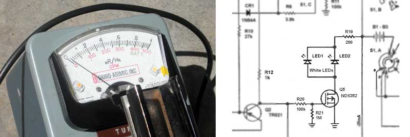
The driver (Q5) takes the signal from the mono stable oscillator (Q1,Q2), and lights the LEDs for the duration of the pulse. The input resistance of MOSFET transistor does not affect to the circuit's operation.
Sound.
It's nice to have a sound, too. And not only because after 5 minutes it becomes boring to look at the indicator's arrow. After a short use of the device, you will remember how the normal background sounds. And if something changes, you can confirm it.
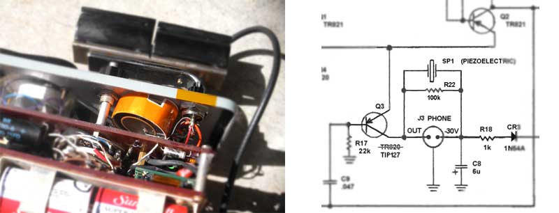
The piezoelectric speaker was chosen only because it does not require changes in the circuit and can work directly. PZ speaker from the old phone, and resistor R22 (100k) discharges the membrane in the gap between pulses. All together creates a perfect clicking sound.
***The transistor Q3 (TR820) should be replaced with any high voltage PNP transistor, as the voltage, constantly present at its collector, is about -35V (DC).
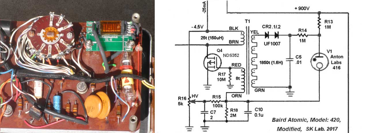
900V converter.
At the first time, the circuit was modified as follows. It consumed about 25 mA at 4V.
When
the output voltage rises above 950 volts, a positive voltage appears on
R18, which closes the transistor Q4 and the converter stops. When the
output voltage drops, the converter turns on again.
It worked for several months and died when replacing the batteries. It was found out that the circuit is OVER-sensitive to input voltage, temperature and settings of R16. In addition, a current consumption (25mA) kills the batteries after 10 days of continuous operation.
The previous circuit has tons of other shortcomings that describe very long. So we chose a different type of converter, which is impossible to kill and work as is. The heart of the circuit, which works up to this day:
The disadvantage is that you must calculate and rewind new transformer, which is usually taken from any LCD monitor. But this is done very simply, as follows.
Take a suitable transformer from any old LCD monitor and remove the low-voltage winding. Count the number of turns. For me it was 26 turns, transformer works from 12 volts, it means ~ 2 turns per Volt.
Suppose that the converter must operate from a voltage of 3 to 5 volts. Hence, the collector's winding must contain 6 to 10 turns. The base winding must produce 3 to 4 volts, it is 6 to 8 turns. If you not very scrupulous, then three winding, 8 turns each, will do the trick. Rewind the transformer, connect it to the circuit above and it will immediately start working.
And of course, not without flaws. First, the output voltage depends on battery voltage. In the range of 3 to 4.5V, the output voltage will float from 700V to 1500V. The second, since we have a bias current for transistors, the total current consumption will be ~ 40 mA.
Both these shortcomings must be eliminated, even if the circuit becomes a bit more complicated. But it's worth it.
The circuit works as follows. When power is supplied, the Q3 & Q4 operates in low power mode. Next, C2 charged to 1.5V, Q2 opens and output voltage increases. When the latter reaches + 950V, the voltage on the R4 rises. This opens Q1, closes Q2 and the circuit goes into low consumption mode. When the output voltage drops below 900V, the cycle repeats again. Capacitors C1,C2 provide .5 sec delay. LED1 & LED2 never light up, and operate as zeners to protect gate of Q1.
I am far from the idea that someone will be able to repeat this circuit (except China), but if you do this and have some questions, then my e-mail is at the bottom of this page.
OK. Now it's time for something to get some fun. The next page will show how to make this piece of s... to something useful and reliable, that can be used as an accurate device to monitor the level of natural radiation and, in a bad case scenarios, for something more.
*** It was interesting to find a book dated 1946, and read about the radiation hazard.
Several chapters from it you can read too.
Several chapters from it you can read too.
1.MEASUREMENT OF NUCLEAR RADIATIONS.
2.DECONTAMINATION.
3.EFFECT ON PERSONNEL.
4.PROTECTION OF PERSONNEL.
2.DECONTAMINATION.
3.EFFECT ON PERSONNEL.
4.PROTECTION OF PERSONNEL.
In case of inaccuracies - let me know. The address is below.