
For reference only.
Pulse generator for Geo Radar + my reminder.
9b.0 Schematic.
The whole idea was to quickly make a short pulse generator for the GeoRadar , and check what the minimum pulse length can be obtained. Final schem. is here, jic.
Therefore, everything is simplified to the point of impossibility. The generator on three inverters of SN74HC04 (on two inv. is described here) generates a frequency of 220 kHz, with a duty cycle close to 50%, and the trigger receives these pulses at the synchronization input "C". When the front edge of the pulse arrives (these type of triggers (74x74) are latched on the rising edge on "C"), the flip-flop is set, and immediately reset by the reset signal on "R" (this is an unconditional reset, does not depend on any other conditions).
Just like this and everything you want to know is on the schematic diagram.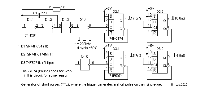
* Two triggers are connected in series in order to determine the delay time, as well as whether they can work from extremely short pulses.
Actually, that's all. GPR requires short pulses and this is how you can get them with a minimum of headache, without calculating the RC-time and picking up elements. The rest is only for curious people.
If you want to get some fun with an oscilloscope.
9b.1 The main generator on three inverters.
Moving away from the topic, the main generator on three inverters is interesting itself. It works under any conditions, if you have correctly selected the resistance of R1. It should be within 100's ohms to kilo-ohms, for TTL.
The animated picture shows oscillograms at the inputs of inverters of D1. The pin number appears in the upper right corner. The rising time is in the last picture.

I didn't expect anything else, it's very predictable. The first picture shows how the capacitor C1 is charged and discharged through the resistor R1. Output of D1.1, we have excellent rectangular pulses, and at the output D1.3 the same thing, only with a delay. This can be used too.
9b.2 Short pulses at the outputs of fast and slow triggers.
Sorry. Because the page does not hold up second animated gif image it is carried over to the next page.
9b.3 Delay for each trigger.

It's easy to see ~9 nS latency because a lot is going on under the hood : )
For a faster trigger 74F5074, the oscillogram looks less attractive since it was taken with 100 MHz probes. But nonetheless:
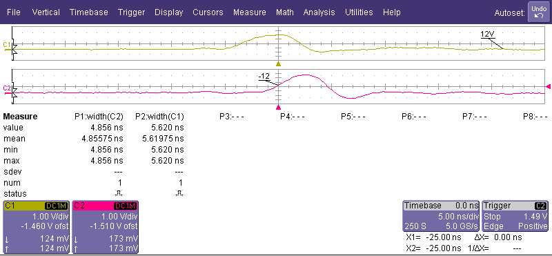
Here the delay is about 3.5 nanoseconds, which is predictable, the same.
Actually, that's all I need to know :)
Additionally, for a note: